DIY ESP8266 Development Board

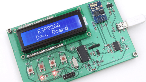
Those small, super-cheap, ESP8266 modules are being installed everywhere, creating all sorts of frivolous internet connected thingamajigs. But consider this period as a training ground of sorts, as hackers smarten their chops on figuring out how to get the best out of this IoT gravy train. Right now, getting the ESP8266 to work requires a fair amount of work and to make things easier, [Abdulgafur] built a ESP8266 development board.

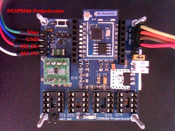
The dev board lets the user connect the ESP8266 to a PIC micro controller as well as to a host PC. In addition, it hosts several peripherals such as a 2×16 LCD display, 4 push buttons, couple of indicator LEDs and some GPIO’s broken out to a header. PC communication is via a FT232RL USB-UART converter over a Mini-USB connector. There’s also a few bi-directional level converters to translate between 5V and 3.3V and pull-up resistors for the ESP8266.

As of now, the dev board only supports the ESP8266-01 module. A nice upgrade would be to add support for other ESP8266 modules too. Maybe a separate, 3d printed, pogo pinned, test fixture for the other modules. If you plan to build you own version, [Abdulgafur] has the schematic, PCB and BoM available for download, although we couldn’t spot the PIC code, so you might have to ask for that. And it would be a good idea to remove the GND copper pour from under the ESP8266 footprint.

ESP8266 Keeps An Eye On Your Batteries

There are many more things to know about a battery than its voltage and current output at any given moment, and most of them can’t be measured with a standard multimeter unless you also stand there for a long time with an Excel spreadsheet. The most useful information is battery capacity, which can tell you how much time is left until the battery is fully charged or fully discharged. [TJ] set out to create a battery data harvester, and used the ubiquitous ESP8266 to make a fully-featured battery monitor.

Measuring battery capacity is pretty straightforward but it does take time. A battery is first benchmarked to find its ideal capacity, and then future voltage and current readings can be taken and compared to the benchmark test to determine the present capacity of the battery. The ESP8266 is a relatively good choice for this kind of work. Its WiFi connection allows it to report its information to a server which will store the data and make it available for the user to see.

The first page of this project details building the actual module, and the second page outlines how to get that module to communicate with the server. Once you’ve built all of this, you can use it to monitor your whole-house UPS backup system or the battery in your solar-powered truck. There is quite a bit of information available on the project site for recreating the build yourself, and there’s also a video below which shows its operation.

Continue reading “ESP8266 Keeps An Eye On Your Batteries”

Hackaday Prize Entry : Subterranean Positioning System

There are numerous instances where we need to know our location, but cannot do so due to GPS / GSM signals being unavailable and/or unreachable on our Smart Phones. [Blecky] is working on SubPos to solve this problem. It’s a WiFi-based positioning system that can be used where GPS can’t.

SubPos does not need expensive licensing, specialized hardware, laborious area profiling or reliance on data connectivity (connection to database/cellphone coverage). It works independently of, or alongside, GPS/Wi-Fi Positioning Systems (WPS)/Indoor Positioning Systems (IPS) as an additional positioning data source by exploiting hardware commonly available.

As long as SubPos nodes are populated, all a user wishing to determine their location underground or indoors needs to do is use a Wi-Fi receiver.  This can be useful in places such as metro lines, shopping malls, car parks, art galleries or conference centers – essentially anyplace GPS doesn’t penetrate. SubPos defines an accurate method for subterranean positioning in different environments by exploiting all the capabilities of Wi-Fi. SubPos Nodes or existing Wi-Fi access points are used to transmit encoded information in a standard Wi-Fi beacon frame which is then used for position triangulation.

The SubPos Nodes operate much like GPS satellites, except that instead of using precise timing to calculate distance between a transmitter and receiver, SubPos uses coded transmitter information as well as the client’s received signal strength. Watch a demo video after the break.


The 2015 Hackaday Prize is sponsored by:

Continue reading “Hackaday Prize Entry : Subterranean Positioning System”

robotic dog

Robot K-9 Scares Off The Daleks

[Bithead942’s] love of the ever popular Dr Who series led her to develop a replica of the 4th Doctor’s robotic companion. It’s name is K-9, and was built from scratch in only 4 months. Its shell is made from HPDE – a light and bendable plastic. A custom plastic bender was constructed to get the angles just right, and custom laser cut parts were used in various places.

Its frame consists of aluminum channel, and is packed full of juicy electronics. An arduino with an XBee shield controls the remote voice, frickin’ laser and eye sensors. Another arduino is paired with a motor shield to control the linear actuator for the neck movement. And a Raspberry Pi keeps the LCD screen in order.

We’re not done, folks. Because this puppy is radio controlled, a custom controller is needed. Sparkfun’s Fio paired with another XBee is used along with a 16×2 LCD and various other electronics to keep the robot on an invisible leash.

Be sure to check out the blog site, as it goes into great detail on all the various parts used to construct this complicated but awesome project.

wireless reset button

Door Bell Used To Reset WiFi Router

We’ve all have had to reset our routers or modems at some point because they were acting up. The typical scenario is; unplug the device, wait 30 seconds, plug it back in and wait for it to boot back up. While not hard, this can be an annoyance, especially if accessing the router or power cord is inconvenient. [Taylor] wrote in to tell us about his wireless router that seems to need to be reset more than he’d like. Although the simplest solution may be to get a new router, he thought it would be fun to do something a little more exciting by making a wireless reset controller.

[Taylor] started with an ordinary power strip. He spliced in a relay to the hot side of the AC line, connected to the common and normally-closed pins of the relay. That way, when the relay is not activated, the power strip is powered. Next, a wireless doorbell was re-purposed to act as the transmitter and receiver. The speaker was removed and the output lines connected to a mono-stable 555 timer circuit that [Taylor] made. When the circuit receives a signal from the door bell speaker lines, it will activate the relay for about 30 seconds. Since the relay was wired to supply voltage to the power strip when not activated, activating the relay cuts the power for 30 seconds effectively resetting the router. Now, whenever the router needs a reset, doing so is as easy as pushing the door bell button from anywhere in the house.

The Digistump Oak; An ESP8266 On Kickstarter

When it was first released, the ESP8266 was a marvel; a complete WiFi solution for any project that cost about $5. A few weeks later, and people were hard at work putting code on the tiny little microcontroller in the ESP8266 and it was clear that this module would be the future of WiFi-enabled Things for the Internet.

Now it’s a Kickstarter Project. It’s called the Digistump Oak, and it’s exactly what anyone following the ESP8266 development scene would expect: WiFi, a few GPIOs, and cheap – just $13 for a shipped, fully functional dev board.

The guy behind the Oak, [Erik Kettenburg], has seen a lot of success with his crowdfunded dev boards. He created the Digispark, a tiny, USB-enabled development board that’s hardly larger than a USB plug itself. The Digispark Pro followed, getting even more extremely small AVR dev boards out in the wild.

The Digistump Oak moves away from the AVR platform and puts everything on an ESP8266. Actually, this isn’t exactly the ESP8266 you can buy from hundreds of unnamed Chinese retailers; while it still uses the ESP8266 chip, there’s a larger SPI Flash, and the Oak is FCC certified.

Yes, if you’re thinking about building a product with the ESP8266, you’ll want to watch [Erik]’s campaign closely. He’s doing the legwork to repackage the ESP into something the FCC can certify. Until someone else does it, it’s a license to print money.

The FCC-certified ESP8266 derived module, cleverly called the Acorn, will be available in large quantities, packaged in JEDEC trays sometime after the campaign is finished. It’s an interesting board, and we’re sure more than one teardown of the Acorn will hit YouTube when these things start shipping.

Switch Mains Power With An ESP8266

Before we begin, we must begin with an obligatory disclaimer: handling mains voltage can be very dangerous. Do not do so unless you are qualified! You could burn your house down. (Without the lemons.) That being said, [TJ] has created an interesting dev board for controlling mains voltage over WiFi with the now-ubiquitous ESP8266 module. At only 50mm x 25mm, it is easily small enough to fit inside a junction box!

Called the MPSMv2, the core of the project is the ESP8266 module. The dev board itself can support anything with GPIO pins, whether it’s an Arudino, Raspberry Pi, or anything else with those features. Flashing the NodeMCU firmware is pretty much all that needs to be done in order to get the device up and running, and once you get the device connected to your WiFi you’ll be able to control whatever appliances you want.

The device uses a triac to do the switching, and is optically isolated from mains. Be sure to check out the video after the break to see the device in action. All in all, this could be a great way to get started with home automation, or maybe just do something simple like build a timer for your floor lamp. Anything is possible!

Continue reading “Switch Mains Power With An ESP8266”