3D printed gearboxes are great for experimental designs, but due to roughness and inaccuracies in the printed surfaces, they can wear quickly and be rather noisy. As a possible alternative, [Resetman] is experimenting with magnetic 3D printed gearboxes that work without physical contact between the rotating wheels, and can also be “geared” for different ratios in some interesting ways.
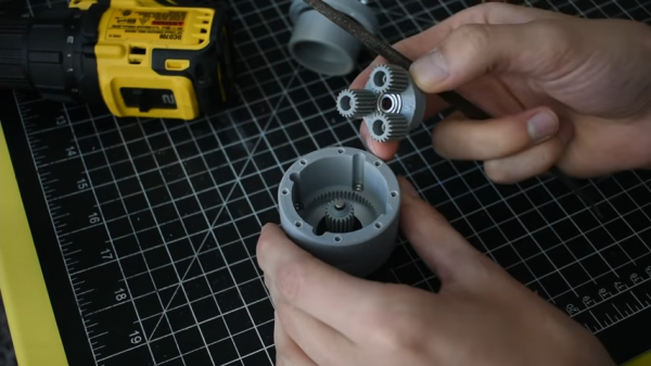
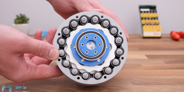
Naturally, two closely spaced wheels with magnets will interact with each other, with the ratio defined by the number of magnets on each wheel. A much less obvious implementation is a second-order radial flux coaxial magnetic gearbox. It works similar to a normal planetary gearbox, with an outer and inner wheel containing magnets, and an intermediate ring known as a flux modulator, containing equally spaced pieces of ferromagnetic steel metal. In [Resetman] demonstration, the flux modulator is just a 3D printed ring screws around its circumference.
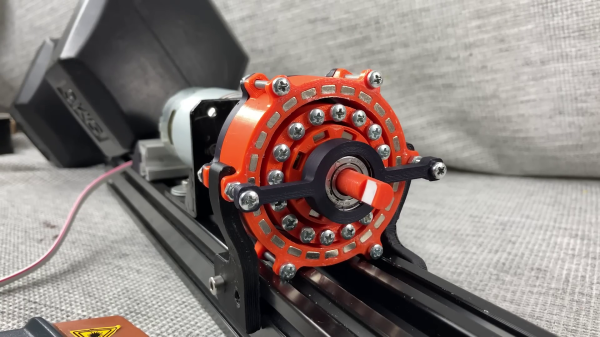
The most obvious disadvantage is of course severely limited torque transfer. [Resetman] could easily accelerate the sun wheel to 12,000 RPM if the flux modulator is accelerated slowly, but any sudden changes in speed would cause it to lose synchronization. Of course, you can consider this a torque-limiting feature for certain use cases. With a bit of testing, he determined the torque limit at a 1:4 ratio was a meager 0.05 Nm. This could be increased by some optimization, for example rearranging the magnets to form Halbach arrays, and reducing the air gaps between the components.
Magnetic gearboxes are nothing new, we’ve featured another demonstrator before, and even did an “Ask Hackaday” on the subject. What would you use these for? Let us know below.
Continue reading “Magnetic Gearbox Can Go Fast But Not Hard”