When designing even a reasonably simple 3D-printable part, you need to account for all the supports it will require to print well. Strategic offsetting, chamfering, and filleting are firmly in our toolkits. Over time we’ve learned to dial our settings in so that, hopefully, we don’t have to fumble around with a xacto knife after the bed has cooled down. On Twitter, Chris shows off his foldable 3D print experiments (nitter) that work around the support problem by printing the part as a single piece able to fold into a block as soon as you pop it off the bed.
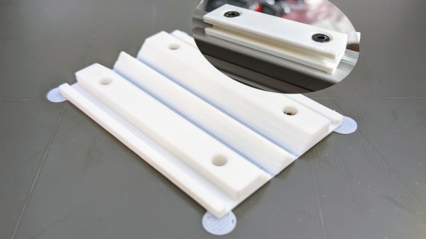
The main components of this trick seem to be the shape of the place where the print will fold, and the alignment of bottom layer lines perpendicular to the direction of the fold lines. [Chris] shows a cross-section of his FreeCad design, sharing the dimensions he has found to work best.
Of course, this is Twitter, so other hackers are making suggestions to improve the design — like this sketch of a captive wedge likely to improve alignment. As for layer line direction alignment, [Chris] admits to winging it by rotating the part in the slicer until the layer lines are oriented just right. People have been experimenting with this for some time now, and tricks like these are always a welcome addition to our toolkits. You might be wondering – what kinds of projects are such hinges useful for?
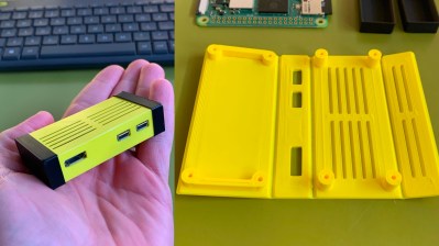 The example Chris provides is a Eurorack rail segment — due to the kind of overhangs required, you’d be inclined to print it vertically, taking a hit to the print time and introducing structural weaknesses. With this trick, you absolutely don’t have to! You can also go way further and 3D print a single-piece foldable Raspberry Pi Zero case, available on Printables, with only two extra endcaps somewhat required to hold it together.
Foldable 3D prints aren’t new, though we typically see them done with print-in-place hinges that are technically separate pieces. This trick is a radical solution to avoiding supports and any piece separation altogether. In laser cutting, we’ve known about similar techniques for a while, called a “living hinge”, but we generally haven’t extended this technique into 3D printing, save for a few manufacturing-grade techniques. Hinges like these aren’t generally meant to bend many times before they break. It’s possible to work around that, too — last time we talked about this, it was an extensive journey that combined plastic and fabric to produce incredibly small 3D printed robots!
We thank [Chaos] for sharing this with us!