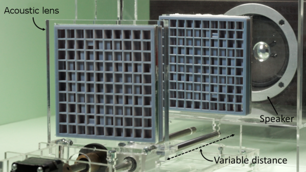
Acoustic lenses are remarkable devices that just got cooler. A recent presentation at SIGGRAPH 2019 showed that with the help of 3D printing, it is possible to build the acoustic equivalent of optical devices. That is to say, configurations that redirect or focus sound waves. One fascinating demonstration worked like an acoustic prism, able to send different notes from a simple melody in different directions. Another was a device that dynamically varied the distance between two lenses in order to focus sound onto a moving target. In both cases, the sounds originate from an ordinary speaker and are shaped by passing through the acoustic lens or lenses, which are entirely passive devices.
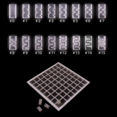 Researchers from the University of Sussex used 3D printing for a modular approach to acoustic lens design. 16 different pre-printed “bricks” (shown here) can be assembled in various combinations to get different results. There are limitations, however. The demonstration lenses only work in a narrow bandwidth, meaning that the sound they work with is limited to about an octave at best. That’s enough for a simple melody, but not nearly enough to cover a human’s full audible range. Download the PDF for a quick read about the details, it’s only two pages but loaded with enough to whet your appetite to know more.
Directional sound can be done in other ways as well, such as using an array of ultrasonic emitters to create a coherent beam of sound. Ultrasonic emitters can even levitate lightweight objects. Ain’t sound neat?
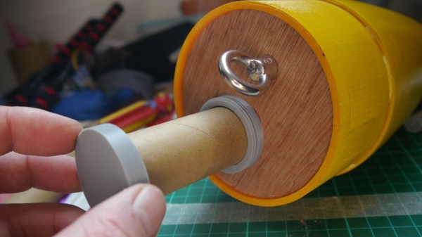
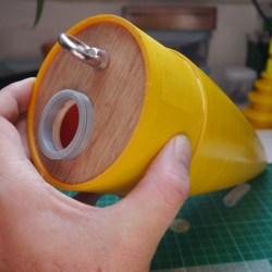 The payload container is a hollow tube with a 3D printed threaded adaptor attached to one end. Payload goes into the tube, and the tube inserts into a hole in the bulkhead, screwing down securely. The result is an easy way to send up something like a GPS tracker, possibly with a LoRa module attached to it. That combination is a popular one with high-altitude balloons, which, like rockets, also require people to retrieve them after not-entirely-predictable landings. LoRa wireless communications have very long range, but that doesn’t help if there’s an obstruction like a hill between you and the transmitter. In those cases,
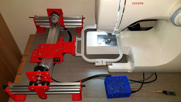
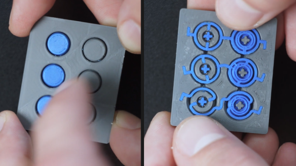
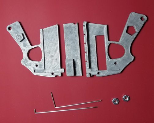
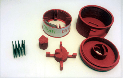 The entire mechanism including the spring is 3D printed, but the spring is PETG and the rest is PLA. [u407] doubts PLA would work for the spring because of how much it gets compressed, but suggests that ABS might work as an alternative.
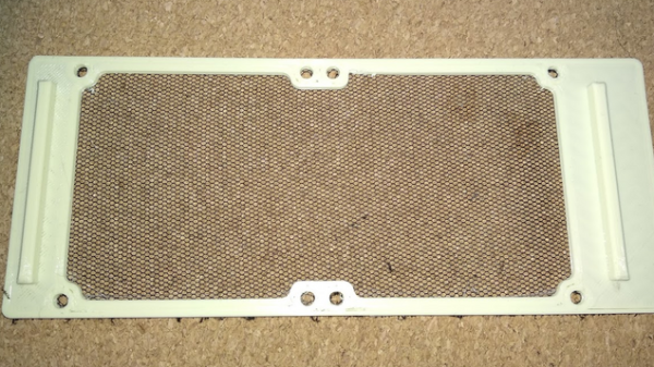
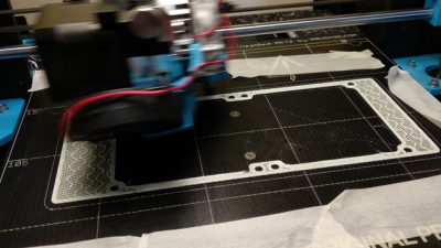 The basic idea is that a 3D print is started, then paused after a few layers. A fine fabric mesh (like tulle, commonly used for bridal veils) is then stretched taut across the print bed, and printing is resumed. If all goes well, the result is 3D printed elements embedded into a flexible, wearable sheet.
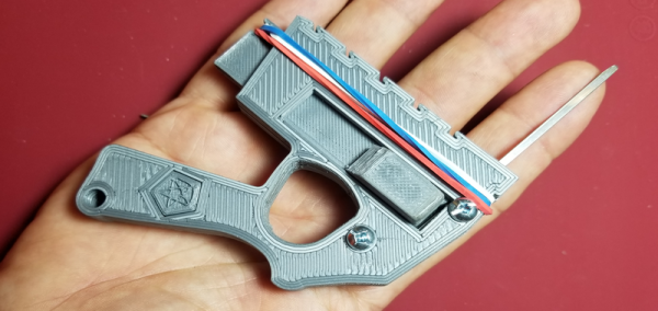
 Now, for us at least, fantasy became a reality as [Peterthinks] makes public his
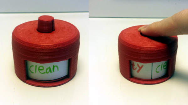
  The device works by manually flicking the spring (rubber band) loaded side switch which then toggles the picking tang up and down whilst simultaneously using another tang to gently prime the opening rotator.