Frame Antenna Works The Low Bands

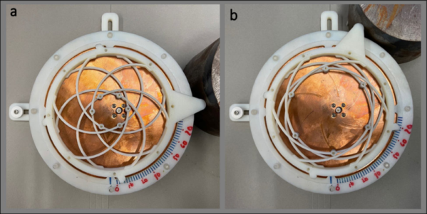
The lower the frequency of radio transmission, the more antenna that will be needed in general. [OM0ET] wanted to work the 80M to 20M ham bands and decided to turn to a frame antenna. You can see the project in the video below.

The antenna looks a lot like a magnetic loop antenna. The one in the video has seven loops forming a 520mm square. The loop is, of course, an inductor and by removing some insulation, the operator can clip a lead at different points to control the inductance. A variable capacitor resonates the antenna, so there is definitely tuning required.

Continue reading “Frame Antenna Works The Low Bands”

An NFC Antenna Ring With A Chip As Its Jewel

Contactless payment by means of NFC-enabled bank cards has made our everyday transactions far more convenient over the last decade, but there still remains the tedious task of finding the card and waving it over the reader. Maybe embedded chips are a step too far for many of us, but how about a bank card in a wearable such as a ring? [Jonathan Limén] shows us how, by taking the NFC chip module from a bank card and mounting it on a ring with a wire coil antenna embedded within it.

The chip in a bank card comes mounted on a small thin PCB with contacts on one side and a coil on the other that serves as its antenna. It’s not sensitive enough to work reliably with most card readers, so the card incorporates a separate printed circuit layer that forms a large-sized tuned circuit which couples to the chip antenna. After taking us through the removal of the chip from the card with some acetone, he proceeds to create a replacement for the card antenna by winding a wire coil round the ring. This becomes a trial-and-error process, but in the end, the result is a working NFC payment ring.

We quite like this idea, but would be tempted to both take away some of the trial and error with a vector network analyzer, and run a couple of turns of the wire as a closer coupling coil for the chip. This is a subject we’ve looked at before here at Hackaday, and we wouldn’t mind having another go at it.

NFC Performance: It’s All In The Antenna

NFC tags are a frequent target for experimentation, whether simply by using an app on a mobile phone to interrogate or write to tags, by incorporating them in projects by means of an off-the-shelf module, or by designing a project using them from scratch. Yet they’re not always easy to get right, and can often give disappointing results. This article will attempt to demystify what is probably the most likely avenue for an NFC project to have poor performance, the pickup coil antenna in the reader itself.

A selection of the NFC tags on my desk

The tags contain chips that are energised through the RF field that provides enough power for them to start up, at which point they can communicate with a host computer for whatever their purpose is.

“NFC” stands for “Near Field Communication”, in which data can be exchanged between physically proximate devices without their being physically connected.  Both reader and tag achieve this through an antenna, which takes the form of a flat coil and a capacitor that together make a resonant tuned circuit. The reader sends out pulses of RF which is maintained once an answer is received from a card, and thus communication can be established until the card is out of the reader’s range. Continue reading “NFC Performance: It’s All In The Antenna”

Add Mycelium To Your Mesh Networks

In many parts of the world, days after a good rainfall, it’s fairly common to see various species of mushrooms popping up out of the ground. These mysterious organisms aren’t the whole story, though. The living being is a vast network of hidden fibers, called mycelium, spreading through the ground and into any other organic material it can colonize. Its air of mystery and its vast reach are the inspiration for entire Star Trek shows and, of course, projects like this LoRa-based mesh network called Mycelium.

Mycelium is the invention of [Catamine] and includes many novel features compared to more typical mesh networks. For one, it is intended to be used in low power applications to give users the ability to send messages over a distributed network rather than a centralized network like a cell phone service provider. For another, the messages are able to be encrypted and authenticated, which is not currently possible with other mesh networks such as APRS. The idea is that a large network of people with nothing more complicated than an ESP32, an antenna, and this software would be able to communicate securely in situations where a centralized network is not available, whether that is from something like a natural disaster or from a governmental organization disabling the Internet during a political upheval.

The mesh network is currently in active development, and while messages can not yet be sent, the network is able to recognize nodes and maintain a keybase. There are certainly plenty of instances where something like this would be useful as we’ve seen before from other (non-encrypted) LoRa-based network solutions which are built around similar principles.

Thanks to [dearuserhron] for the tip!

Hackaday Links Column Banner

Hackaday Links: October 3, 2021

It’s one thing to speculate about what’s happening with the Mars helicopter Ingenuity, but it’s another to get an insider’s view on recent flight problems. As we previously reported, Ingenuity is starting to face a significant challenge, as a seasonal atmospheric pressure drop on Mars threatens to make the already rarefied air too thin to generate useful lift. Mission controllers tested the chopper at higher rotor speeds, and while that worked, later attempts to fly using that higher speed resulted in an abort. The article, written by one of the NASA/JPL engineers, is a deep dive into the problem, which occurred when Ingenuity sensed excessive wiggle in two of the servos controlling the rotor swashplate. The thought is that accumulated wear in the servos and linkages might be causing the problem; after all, Ingenuity has made thirteen flights so far, greatly exceeding the five flights originally programmed for it. Here’s hoping they can adapt and keep the helicopter flying, but whatever they do, it’ll have to wait a few weeks until Mars completes its conjunction and pops back out from behind the Sun.

With all the attention understandably paid to the recent 20th anniversary of the 9/11 terror attacks, it’s easy to forget that barely a month after that day, a series of what appeared to be follow-on attacks started: the Anthrax Attacks. Members of Congress and media outlets were targeted via the mail with highly refined anthrax spores, leading to the deaths of five people, with dozens more injured and exposed to anthrax. IEEE Spectrum has an interesting article that goes into some of the technology that was rapidly deployed in an attempt to sanitize the mail, including electron beam and X-ray irradiation to kill any spores. The article also points out how this wasn’t the first time people were afraid of the mail; outbreaks of yellow fever in 1899 led to fumigation of the mail with sulfur, after perforating it with a wicked-looking paddle.

Attention PCB-design newbies — now’s your chance to learn the entire PCB design process from the ground up, with the guidance of industry professionals. TeachMePCB is back again this year, offering to teach you everything you need to know about properly laying out a PCB design in pretty much any EDA software you want. The course requires a two- to five-hour commitment every week for two months, after which you’ll have designed a PCB for a macropad using a Raspberry Pi Pico. The course facilitator is Mark Hughes from Royal Circuits, who did a great Hack Chat with us last year on PCB finishes. This seems like a great way to get up to speed on PCB design, so if you’re interested, act soon — 460 people are already signed up, and the deadline is October 10.

Some of us really love factory tours, no matter what the factory is making. All the better when the factory makes cool electronics stuff, and better still when it’s our friends at Adafruit showing us around their New York City digs. True, it’s a virtual tour, but it has pretty much become a virtual world over the last couple of years, and it’s still a great look inside the Adafruit factory. Hackaday got an in-person tour back in 2015, but we didn’t know their building used to be a Westinghouse radio factory. In fact, the whole area was once part of the famed “Radio Row” that every major city seemed to have from the 1920s to the 1960s. It’s good to get a look inside a real manufacturing operation, especially one that’s right in the heart of a city.

And finally, those with a fear of heights might want to avoid watching this fascinating film on the change-out of a TV transmitter antenna. The tower is over 1,500′ (450 m) tall, lofting an aging antenna over the flat Florida terrain. Most of the footage comes from body-mounted cameras on the riggers working the job, including the one very brave soul who climbed up the partially unbolted antenna to connect it to the Sikorsky S64 Skycrane helicopter. It’s a strange combination of a carefully planned and slowly executed ballet, punctuated by moments of frenetic activity and sheer terror. The mishap when releasing the load line after the new antenna was placed could easily have swept the whole rigging crew off the antenna, but luckily nobody was injured.

Continue reading “Hackaday Links: October 3, 2021”

A Bird 43 wattmeter and its homebrew equivalent

Homebrew Wattmeter Pays Homage To Sturdy Original

If there’s one instrument that hams and other radio enthusiasts covet, it’s the venerable Bird 43 Thruline wattmeter. The useful RF tool has barely changed in the nearly 70 years since it was first introduced, and they’re built like a tank. This makes Bird meters highly desirable, and therefore quite expensive either brand new or on the swap-meet circuit.

But radio amateurs are nothing if not resourceful, and building a homebrew version of the Bird wattmeter (in Portuguese; Google translate tool at the bottom of the page) as Brazilian ham [Luciano Sturaro (PY2BBS)] did is a good way to get your hands on one. Granted, [Luciano] had a head start: a spare line set, which is the important bit from a Bird wattmeter. The machined metal part is in effect an air-insulated section of coaxial cable that the RF signal passes through on its way from transmitter to antenna. A “slug” is inserted into the cavity in the line set to sense the RF and couple it to the meter electronics; the slug can be rotated to measure RF traveling in either direction, allowing the user to determine how much RF is getting reflected by the antenna system.

[Luciano]’s version of the meter is faithful to the sturdy construction of the original, with a solid steel case that mimics its classic lines — the case even sports the same color scheme and stout leather carry handle. There are some changes to the electronics, and the meter movement itself is different from the original, but all in all, the “Buzz 50” looks fantastic. We especially love the detailed nameplate as an homage to Bird.

The thing about Bird — and Bird-like — meters is that the slugs are like potato chips; you can’t have just one. Curious as to how these slugs work? Check out this slug repair project.

[Featured image of Bird 43 Wattmeter: Martin RF Supply]

Thanks to [Niko Huenk] for the tip!

A 3-6-9 Antenna Pulls In The Signals

Every time we see a dispatch from [Mr. Carlson], we imagine it is being beamed from his orbital station packed full of vintage radio gear. We are certain the reality is more terrestrial, but if we were going to build an orbiting lab, it might look like [Carlson’s] shack. In his latest communique, he shares his progress working on a high-performance 3-6-9 receiving antenna design and you can see it in the video below.

Although the antenna isn’t done, it is already working and looks impressive. There’s a lot of wire, so this probably isn’t a condo-friendly solution. The name of the antenna derives from the three wires, one tuned for 3 MHz, one for 6 MHz, and the other for 9 MHz.

Continue reading “A 3-6-9 Antenna Pulls In The Signals”