Electromagnetic Mechanism Makes Reconfigurable Antenna

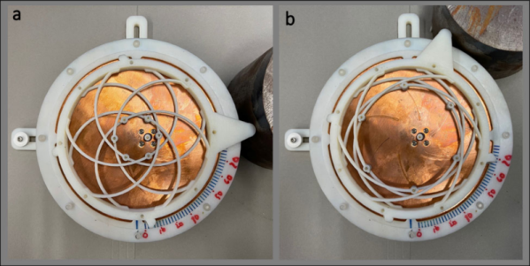
Antennas are a key component to any RF gadget. But antennas often only perform well over a narrow band of frequencies. For some applications, this is acceptable, but often you would like to reconfigure an antenna for different bands. Researchers at Penn State say they’ve developed a tunable antenna using compliant mechanisms and electromagnets. The new scalable design could work in small areas to provide frequency agility or beamforming.

The prototype is a circular patch antenna made with 3D printing. If you want to read the actual paper, you can find it on Nature Communications.

A compliant mechanism is one that achieves force and motion through elastic body deformation. Think of a binder clip. There’s no hinge or bearing. Yet the part moves in a useful way, using its own deformation to open up or grip papers tightly. That’s an example of a compliant mechanism. This isn’t a new idea — the bow and arrow are another example. However, because 3D printing offers many opportunities to build and refine devices like this, interest in them have increased in recent years.

We couldn’t help but notice that the antenna is a variation of a “compliant iris” like the one in the video below. You can find designs for these online for 3D printing, so if you wanted to experiment,  you might think about starting there.

We’ve looked at compliant mechanisms before. Why would you want better chip-scale antennas? Why, indeed.

Continue reading “Electromagnetic Mechanism Makes Reconfigurable Antenna”

Antenna Mount Designed For On-The-Go SDR

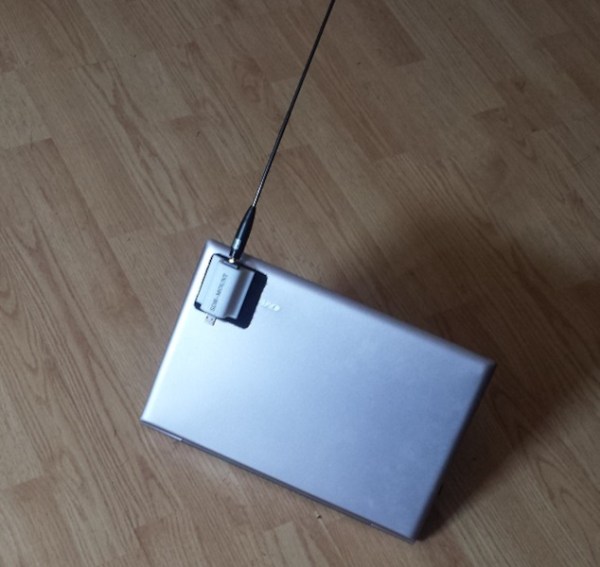
Software-defined radio is all the rage these days, and for good reason. It eliminates or drastically reduces the amount of otherwise pricey equipment needed to transmit or even just receive, and can pack many more features than most affordable radio setups otherwise would have. It also makes it possible to go mobile much more easily. [Rostislav Persion] uses a laptop for on-the-go SDR activities, and designed this 3D printed antenna mount to make his radio adventures much easier.

The antenna mount is a small 3D printed enclosure for his NESDR Smart Dongle with a wide base to attach to the back of his laptop lid with Velcro so it can easily be removed or attached. This allows him to run a single USB cable to the dongle and have it oriented properly for maximum antenna effectiveness without something cumbersome like a dedicated antenna stand. [Rostislav] even modeled the entire assembly so that he could run a stress analysis on it, and from that data ended up filling it with epoxy to ensure maximum lifespan with minimal wear on the components.

We definitely appreciate the simple and clean build which allows easy access to HF and higher frequencies while mobile, especially since the 3D modeling takes it a step beyond simply printing a 3D accessory and hoping for the best. There’s even an improved version on his site here. To go even one step further, though, we’ve seen the antennas themselves get designed and then 3D printed directly.

AntRunner Is The Satellite Antenna Mount You Need To Take With You

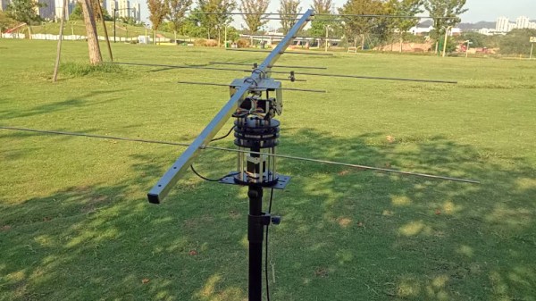
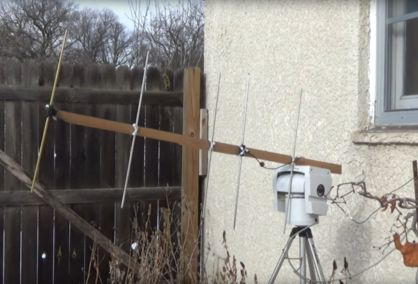
It stands to reason, that should you wish to communicate with a satellite, whatever antenna you use should point at that satellite. Some of us have done this by hand, following the bright dot of the space station in the night sky. Still, for anything more serious than trying to catch a fleeting SSTV image, a more robust solution is called for. In other words, a motorized antenna rotator, and AntRunner from [Wuxx] is just the ticket. Better still, it’s portable for those /p operating sessions off the beaten track.

The rotator itself is an az-el design with a couple of geared stepper motors. The full mechanism design has been published, but it shouldn’t be too difficult to copy. The interesting part is the controller and software, which can work with Gpredict, Hamlib, and SDR for automated satellite tracking. The controller is as straightforward as an ESP32 running the ESP port of GRBL.

So here’s a portable antenna rotator that’s accessible and widely supported, what’s not to like? As you might expect though, it’s not the first we’ve seen. In fact, the 2014 Hackaday Prize was won by SatNOGs, which includes a 3D printed antenna positioner.

Thanks [Abe Tusk] for the tip!

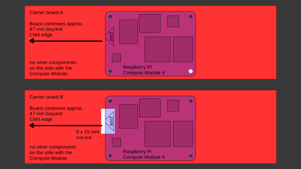
Sketch of the two proprietary carriers showing their differences - one of them has a cutout under the antenna, while the other one does not.

Design Your CM4 Carrier With WiFi Performance In Mind

The Raspberry Pi Compute Module 4 has a built-in WiFi antenna, but that doesn’t mean it will work well for you – the physical properties of the carrier board impact your signal quality, too. [Avian] decided to do a straightforward test – measuring WiFi RSSI changes and throughput with a few different carrier boards. It appears that the carriers he used were proprietary, but [Avian] provides sketches of how the CM4 is positioned on these.

There’s two recommendations for making WiFi work well on the CM4 – placing the module’s WiFi antenna at your carrier PCB’s edge, and adding a ground cutout of a specified size under the antenna. [Avian] made tests with three configurations in total – the CMIO4 official carrier board which adheres to both of these rules, carrier board A which adheres to neither, and carrier board B which seems to be a copy of board A with a ground cutout added.

Graph plotting WiFi RSSI for each of the three carriers in each of the six locations. CMIO4 consistently outperforms both, while carrier B outperforms the carrier A, but by a more narrow margin.After setting up some test locations and writing a few scripts for ease of testing, [Avian] recorded the experiment data. Having that data plotted, it would seem that, while presence of an under-antenna cutout helps, it doesn’t affect RSSI as much as the module placement does. Of course, there’s way more variables that could affect RSSI results for your own designs – thankfully, the scripts used for logging are available, so you can test your own setups if need be.

If you’re lucky to be able to design with a CM4 in mind and an external antenna isn’t an option for you, this might help in squeezing out a bit more out of your WiFi antenna. [Avian]’s been testing things like these every now and then – a month ago, his ESP8266 GPIO 5V compatibility research led to us having a heated discussion on the topic yet again. It makes sense to stick to the design guidelines if WiFi’s critical for you – after all, even the HDMI interface on Raspberry Pi can make its own WiFi radio malfunction.

A handheld device to measure electromagnetic fields

Measuring Electromagnetic Fields With Just An Arduino And A Piece Of Wire

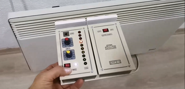
Electromagnetic interference problems can be a real headache to debug. If you need to prove what causes your WiFi to slow down or your digital TV signal to drop, then the ability to measure electromagnetic fields (EMF) can be a big help. Professional equipment is often very expensive, but building an EMF detector yourself is not even that difficult: just take a look at Arduino expert [Mirko Pavleski]’s convenient hand-held electromagnetic field detector.

The basic idea is quite simple: connect an antenna directly to an Arduino’s analog input and visualize the signal that it measures. Because the input of an ADC is high impedance, it is very sensitive to any stray currents that are picked up by the antenna. So sensitive in fact, that a resistor of a few mega-Ohms to ground is required to keep the sensor from triggering on any random kind of noise. [Mirko] made that resistance adjustable with a few knobs and switches so that the detector can be used in both quiet and noisy environments.

Making the whole device work reliably was an interesting exercise in electromagnetic engineering: in the first few iterations, the detector would trigger off its own LEDs and buzzer, trapping itself in a never-ending loop. [Mirko] solved this by encasing the Arduino inside a closed, grounded metal box with only the required wires sticking out. The antenna’s design was largely based on trial-and-error; the current setup with a 7 cm x 3 cm piece of aluminium sheet seemed to work well.

While this is not a calibrated professional-grade instrument, it should come in handy to find sources of interference, or even simply to locate hidden power cables. You can view this as a more advanced version of [Mirko]’s Junk Box EMF Detector; if you have a second Arduino lying around, you can use that one to generate interference instead. Continue reading “Measuring Electromagnetic Fields With Just An Arduino And A Piece Of Wire”

Wind-Up Tape Measure Transformed Into Portable Ham Antenna

If there’s one thing that amateur radio operators are good at, it’s turning just about anything into an antenna. And hams have a long history of portable operations, too, where they drag a (sometimes) minimalist setup of gear into the woods and set up shop to bag some contacts. Getting the two together, as with this field-portable antenna made from a tape measure, is a double win in any ham’s book.

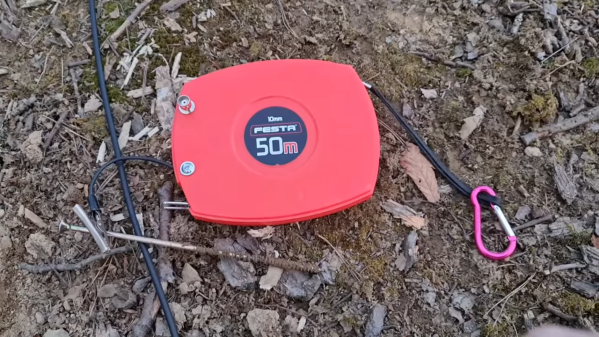
For [Paul (OM0ET)], this build seems motivated mainly by the portability aspect, and less by the “will it antenna?” challenge. In keeping with that, he chose a 50-meter steel tape measure as the basis of the build. This isn’t one of those retractable tape measures, mind you — just a long strip of flexible metal on a wind-up spool in a plastic case. His idea was to use the tape as the radiator for an end-fed halfwave, or EFHW, antenna, a multiband design that’s a popular option for hams operating from the 80-m band down to the 10-m band. EFHW antennas require an impedance-matching transformer, a miniature version of which [Paul] built and tucked within the tape measure case, along with a BNC connector to connect to the radio and a flying lead to connect to the tape.

Since a half-wave antenna is half the length of the target wavelength, [Paul] cut off the last ten meters of the tape to save a little weight. He also scratched off the coating on the tape at about the 40-meter mark, to make good contact with the alligator clip on the flying lead. The first video below details the build, while the second video shows the antenna under test in the field, where it met all of the initial criteria of portability and ease of deployment.

Continue reading “Wind-Up Tape Measure Transformed Into Portable Ham Antenna”

Retrotechtacular: Measuring TV Audiences With The “Poll-O-Meter”

It may come as a shock to some, but TV used to be a big deal — a very big deal. Sitting down in front of the glowing tube for an evening’s entertainment was pretty much all one had to do after work, and while taking in this content was perhaps not that great for us, it was a goldmine for anyone with the ability to monetize it. And monetize it they did, “they” being the advertisers and marketers who saw the potential of the new medium as it ramped up in early 1950s America.

They faced a bit of a problem, though: proving to their customers exactly how many people they were reaching with their ads. The 1956 film below shows one attempt to answer that question with technology, rather than guesswork. The film features the “Poll-O-Meter System,” a mobile electronic tuning recorder built by the Calbest Electronics Company. Not a lot of technical detail is offered in the film, which appears aimed more at the advertising types, but from a shot of the Poll-O-Meter front panel (at 4:12) and a look at its comically outsized rooftop antenna (12:27), it seems safe to assume that it worked by receiving emissions from the TV set’s local oscillator, which would leak a signal from the TV antenna — perhaps similar to the approach used by the UK’s TV locator vans.

The Poll-O-Meter seems to have supported seven channels; even though there were twelve channels back in the day, licenses were rarely granted for stations on adjacent channels in a given market, so getting a hit on the “2-3” channel would have to be considered in the context of the local market. The Poll-O-Meter had a charming, homebrew look to it, right down to the hand-painted logos and panel lettering. Each channel had an electromechanical totalizing counter, plus a patch panel that looks like it could be used to connect different counters to different channels. There even appears to be a way to subtract counts from a channel, although why that would be necessary is unclear. The whole thing lived in the back of a 1954 VW van, and was driven around neighborhoods turning heads and gathering data about what channels were being watched “without enlisting aid or cooperation of … users.” Or, you know, their consent.

It was a different time, though, which is abundantly clear from watching this film, as well as the bonus ad for Westinghouse TVs at the end. The Poll-O-Meter seems a little silly now, but don’t judge 1956 too hard — after all, our world is regularly prowled by equally intrusive and consent-free Google Street View cars. Still, it’s an interesting glimpse into how one outfit tried to hang a price tag on the eyeballs that were silently taking in the “Vast Wasteland.”

Continue reading “Retrotechtacular: Measuring TV Audiences With The “Poll-O-Meter””