While synthesizers in the music world are incredibly common, they’re not all keyboard-based instruments as you might be imagining. Especially if you’re trying to get a specific feel or sound from a synthesizer in order to mimic a real instrument, there might be a better style synth that you can use. One of these types is the breath controller, a synthesizer specifically built to mimic the sound of wind instruments using the actual breath from a physical person. Available breath controllers can be pricey, though, so [Andrey] built his own.
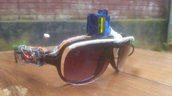
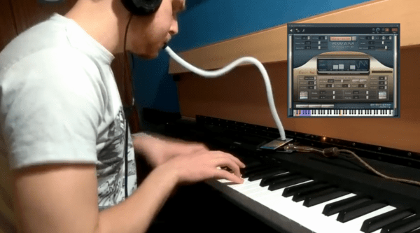
To build the synthesizer, [Andrey] used a melodica hose and mouthpiece connected to a pressure sensor. He then built a condenser circuit on a custom Arduino shield and plugged it all into an Arduino Mega (although he notes that this is a bit of overkill). From there, the Arduino needed to be programmed to act as a MIDI device and to interact with the pressure sensor, and he was well on his way to a wind instrument synthesizer.
The beauty of synthesizers is not just in their ability to match the look and sound of existing instruments but to do things beyond the realm of traditional instruments as well, sometimes for a greatly reduced price point.
Continue reading “Don’t Forget Your Mints When Using This Synthesizer”