We’ve all been there. You are having fun walking around the carnival when you suddenly find yourself walking past the carnival games. The people working the booths are taunting you, trying to get you to play their games. You know the truth, though. Those games are rigged. You don’t know how they do it. You just know that they do… somehow.
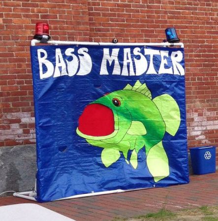
Now you can put your worries to rest and build your own carnival game! [John] built his own “Bass Master 3000” style carnival game and posted an Instructable so you can make one too.
The game is pretty straightforward. You have a giant fish-shaped target with a wide open mouth. You take hold of a small fishing reel with a rubber ball on the end. Your goal is to cast the ball out and hit the fish in its big mouth. If you hit the mouth, you get to hear a loud buzzer and see some flashing lights. The system also uses a webcam to take a candid photo of the winner. A computer screen shows all of the winners of the day.
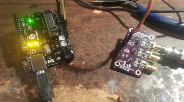
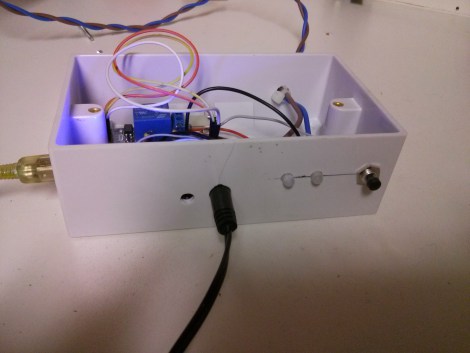
The brain of the system is an Arduino Yún. The Yún is similar to an Uno but it also has some extra features. Some good examples are an Ethernet port, a wireless adapter, and an SD card slot. The mouth sensors are just two piezo elements. Each sensor is hooked up to the Arduino through a small trim pot. This allows you to dial in the sensitivity of each sensor. The lights and the buzzer are controlled via a relay, triggered by a 5V digital pin on the Arduino.
The Yún actually has a small on-board Linux computer that you can communicate with from inside the Arduino environment. This allows [John] to use the Yún to actually take photos directly from a web cam, store them on the local SD card, and display them on a local web server. The web server runs a simple script that displays a slide show of all of the photos stored on the card.
The final piece of the game is the physical target itself. The target is painted using acrylic paint onto a small tarp. The tarp is then attached to a square frame made from PVC pipe. The mouth of the fish is cut out of the tarp. A large piece of felt is then placed behind the hole with the piezo sensors attached. A short length of copper pipe helps to weigh down the bottom of the felt and keep it in place. The important thing is to make sure the felt isn’t touching the tarp. If it touches, it might be overly sensitive and trigger even when a player misses.
Now you know how to build your own Bass Master 3000 carnival game. Whether you rig the game or not is up to you. Also, be sure to check out a video of the system working below. Continue reading “Build A Bass Master 3000 Carnival Game”