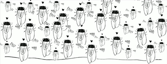
Hacker Sends This Through The Mail To Record A Video Of The Process

[Ruben van der Vleuten] wanted to get a look at the adventure a package experiences when shipped from one place to another. So he threw together this mishmash of components to record the experience. We certainly enjoyed watching the fast motion video found after the break. We wonder what the shipping agency thinks about this sort of thing?

Camera, digital storage, and battery technology have gotten to the point that it’s both cheap and easy to do this sort of surveillance. But there are a few logistical things that [Ruben] took into account to make this work quite well. First off, he need to hide the camera in a way that would ensure the package didn’t look suspicious. He ended up writing his name on the side of the box and boring a hole through one of the black letters which is smaller than a pea and very hard to spot. To make sure he wasn’t recording a ton of empty (dark) frames he also included electronics to sense motion. When the package is moving the video is always rolling. when not moving the hardware wakes for just 3 seconds every minute to shoot video.

Continue reading “Hacker Sends This Through The Mail To Record A Video Of The Process”

Rolling Your Own Minimal USB To Serial Arduino Programmer

usb-to-serial-programmer

[Hans Peter] wanted to move away from using full Arduino boards in his projects. One of the components he rarely used after the development stage is the USB hardware. Once the firmware is flashed to the chip he didn’t need it any longer. So he tried his hand with some really small SMD parts by building this USB to serial Arduino programmer.

The chip he went with isn’t the FTDI part we’re used to. Instead of using an FT232RL, he opted for its smaller cousin the FT230x. This chip doesn’t fully implement the communications protocol of the 232, but it does work with AVRdude and that’s all that really matters. Above you can see [Hans’] creation next to the official Arduino USB-to-serial programmer. He used the same connection scheme, but went with an edge connector for the USB instead of using a mini-B jack.

It’s pretty impressive to see his prototyping work with the 16-pin QFN package. He soldered it dead-bug style to a couple of SIL pin headers in order to test it on a breadboard. The first board he assembled was too loose in the USB port, but he added some tape to the back to make it thicker, and coated the edge connector traces with a bit of solder and that did the trick.

An EQ Display For A Pedal Board

EQ

There are a lot of tinkerers out there who got their start in electronics with musical hacks. Surprisingly though, we don’t see many submissions to our tip line covering boost circuits for electric basses, rewiring guitar electronics, or even more complex effect pedals. [Deadbird], though, is bucking that trend with an EQ display stomp box that fits neatly on his pedal board.

[Deadbird]’s build isn’t a graphic equalizer that can change the volume of different frequency bands; instead, he used the MSGEQ7 chip to listen in on the signal his guitar is producing and display that on a 128×64 graphic backlit display.

The entire project was prototyped on a breadboard with an Arduino. After he got all the components working – a momentary switch to turn the pedal on and off, 1/4″ jacks for the input and output, and a power supply – [Deadbird] took an Arduino prototyping shield and made everything more permanent. Now he’s got an attractive pedal on his board that shows the signal coming from his guitar in seven neat bands.

Hammond Organ Sends Messages Which Can Be Decoded By A Spectrogram

hammond-organ-encodes-messages-spectrogram

Here’s an interesting use for an old organ. Let it get in on your Ham radio action. [Forrest Cook]  is showing off his project which uses a Hammond Organ to encode messages which can be displayed by a Spectrogram. We’ve seen this type of message encoding before (just not involving a musical instrument). It’s rather popular with Hams in the form of the fldigi program.

An Arduino was connected to the organ via a UNL2003 darlington array chip. This chip is driving some reed relays which make the organ connections to create the sine wave tones. With that hardware in place it’s a matter of formatting data to generate the target audio. [Forrest] wrote his own Arduino sketch which takes characters from the serial port (pushed over USB by the laptop), maps then to a stored 5×7 character font set, then drives the pins to produce the tones. As you can see in the clip after the break the resulting audio can be turned into quite readable text.

Continue reading “Hammond Organ Sends Messages Which Can Be Decoded By A Spectrogram”

Atomic Skull Clock Reminds Us We’re Dying

atomic-skull-clock

Whether you like it or not, every second that passes brings you one step closer to your own demise. It’s not a comforting topic to dwell upon, but it’s reality. This art installation entitled ‘Memento Mori’ is a haunting reminder of just that. Even with all the advanced technology we have today, we still have absolutely no way of knowing just when our time will come.

[Martin] cast a real human skull, then added a 4 digit LED display that’s attached to a rubidium atomic clock (running a FE-5680A frequency standard). The display counts down a single second over and over, measured in millisecond-steps, from 1.000 to 0.001. He built a custom electronic circuit to convert the 10 MHz sine wave into a 1 kHz pulse signal, and used ATmega8 chips running an Arduino sketch to do the rest of the dirty work.

Watching the video after the break, with that smooth mysterious music in the background, one can’t help but ponder our mortality. On a personal note, this totally feels like something you’d find in a video game.

[Thanks Martin]

Continue reading “Atomic Skull Clock Reminds Us We’re Dying”

Adding Fireplace Control To Your Home Automation

fireplace-automation

[James] has an admirable home automation system which he’s been working on for years. It does things like monitor the state of the garage door, control the lights, and it even notifies him of a power failure. One thing that wasn’t on the system yet are the fireplaces he has in his home. The hardware you see above is how he patched into the fireplace remote control system in order to automate them.

The remote control uses RF to communicate with a base station. Unlike controlling home theater components which use IR, this makes it a bit more difficult to patch into. Sure, we’d love to see some reverse engineering of the protocol so that a simple radio module could be used, but [James] chose the route which would mean the least amount of hacking on his part. He soldered wires onto the PCB for the buttons and connected to them using reed relays. These let the Arduino simulate button presses.

With the rig connected to the home network he has a lot of options. The system can sense if the house is occupied. If it determines that no one is home it will switch off the fireplaces. [James] also mentions the ability to monitor for carbon monoxide or house fires, switching off the gas fireplaces in either case.

Enabling An Unused Touchscreen Overlay On A Consumer LCD

uncovering-an-unused-touchscreen-on-a-consumer-lcd

When [Andrei] first got his Raspberry Pi he wanted to make it a standalone computer right away. This means the normal input devices like a mouse and keyboard, but also some type of display. To avoid waiting for shipping he ended up using a cheap vehicle backup camera screen from the local big box store. It worked great, and recently he decided he would try to convert it to run off of 5V power to simplify his setup. While snooping around inside the device he discovered an unused resistive touch overlay and figured out how to get it to work.

What tipped him off is the small four-conductor connector which wasn’t hooked up to anything. He carefully soldered wires onto the flexible circuit traces, then generously covered them in hot glue to help prevent movement from breaking the rigid connection. To get this working you need to measure the resistance between the conductors. Most of the time we figure the RPi GPIO header can be used directly, but for this task an intermediary is necessary. [Andrei] went with a small Arduino clone board. A bit of trial and error was all it took to get the connections right and to iron out the code which translates the values into coordinates.