Espresso Upgrade Gives You More Data With Your Caffeine

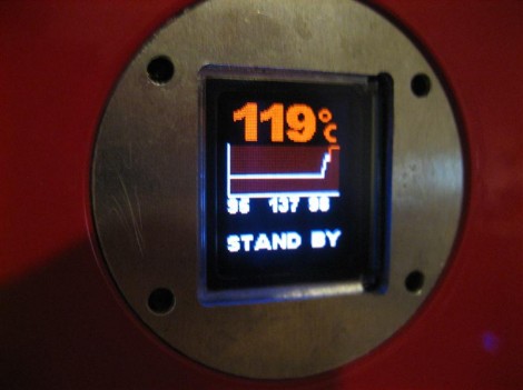
Whether you take it as a single shot or a double, a great Barista want’s to know the details on what’s happening with the espresso machine. [Tobi] was happily generating the morning cup when he realized that the needle-thermometer on his machine wasn’t working any longer. Instead of shelling out a lot of money for a direct replacement, he built his own display and controller for this espresso machine (translated).

He had a few goals with this hack. Obviously he needed to replace the temperature meter, but he also wanted a colorful display and some timing options. He was able to get his hands on a nice little OLED display that would fit in the vacated opening and it only cost a few bucks. He’s got his own mini-mill which came in handy when fabricating a board to host the ATmega16 which drives add-on, but he also used it to make a bracket for the screen replacement.

Now his machine is fixed, looks a bit more modern, and it has more features which are shown off in the video after the break. If you’re looking to add some custom circuitry to your coffee ritual you may also take some inspiration from this similar espresso machine hack. Continue reading “Espresso Upgrade Gives You More Data With Your Caffeine”

Build Your Own Miniature Self Parking Car

self-park

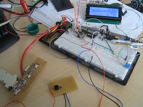
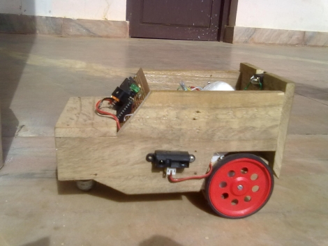
[Achu Wilson] was watching TV when he saw an ad for Volkswagen’s latest Passat, which happens to come equipped with a park assist mode. This essentially allows the car to park itself with little to no user interaction. While these systems come as a pricey add-on option, he figured he could build something similar in his own home, albeit on a much smaller scale.

Digging through his parts bin he only came across a single infrared proximity sensor, so instead of building vehicle that could parallel park, he settled on constructing one that can situate itself in a traditional parking spot instead. The car is built from wood and a pair of DC motors [Achu] had on hand, both of which are controlled using an ATmega16.

As a proof of concept, it looks to work pretty well despite the fact that it only has a single fixed sensor navigate its surroundings. We imagine it would be a relatively easy task to adapt the system for parallel parking, among other things.

Continue reading to see [Achu’s] self-parking car in action.

Continue reading “Build Your Own Miniature Self Parking Car”

Learn The Geometry To Draw An Analog Clock On A Graphic LCD Screen

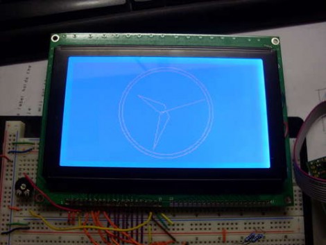
Does the image of the clock above make you shutter with fear because of the math you’d need to use to recreate your own version of the project? We certainly understand that High School geometry is becoming a very distant memory, but it’s really not as hard as you think. [Janw] built this analog clock using a graphic LCD and he’s done a great job of explaining the concepts behind it.

The hardware he’s using is pretty standard for an electronic hobby clock; an ATmega16, graphic LCD, DS1307 real-time clock, and supporting hardware like a potentiometer, resistors, and buttons. The code is written in Bascom, but like we said, [Janw] explains the concepts behind drawing the hands on the clock so you can recreate this with any microcontroller or software language you prefer. We  recommend grabbing a calculator and some blank paper. It took us a few tries to brush the cobwebs out and really grasp what he’s doing with each equation.

Frequency Counter For $10 Worth Of Parts

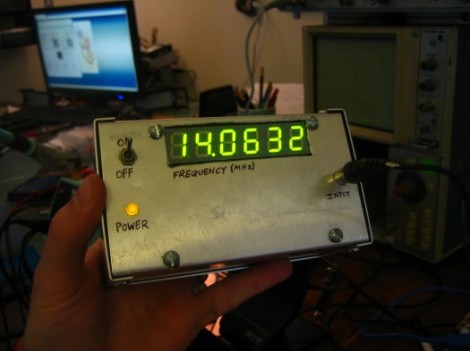
[Scott] built this frequency counter using less than $10 in parts. It’s set up to meter frequencies in megahertz which is fitting since he’s planning to use it with his radio hardware experimentation. But we would find it useful too because our cheap multimeter only reads up to around 4 MHz.

He’s using an ATmega16 that he had on hand but it has features way beyond the specs for the device. He speculates that an ATtiny2313 would easily work in its place. The microcontroller is mostly used to drive the multiplexed 7-segment display after reading the frequency values from the 74LV8154 counter chip that he is using. He doesn’t have a full schematic for the device, but there is a hand drawn diagram for using the frequency counter; the rest should be easy to piece together. Looking at that circuit we don’t think it would be too hard to make this a manual-ranging frequency counter to give you more use out of the dedicated device. Check out [Scott’s] demonstration video which is embedded below the fold.

Continue reading “Frequency Counter For $10 Worth Of Parts”

Playing Piano With Optical Sensors

[Sebastian] is trying to improve the responsiveness of an electric keyboard. He was unsatisfied with the lack of adequate sensitivity to keystroke. The first step in his process was to measure how fast the quickest keystroke actually is. By setting up an LED and phototransistor and taking some measurements he found that sampling at 1 kHz would be more than adequate.

With initial testing complete he ordered some CNY70 transmissive/reflective light sensors that can be place below the keys. He measures the sensor with the ADC on an ATmega16 microcontroller. Running at 16 MHz he can sample each of the eight analog-to-digital converter channels at 1202 Hz. After doing a bunch of math he put together some lookup tables that are used to translate the ADC data into midi signals. We’ve embedded a video of one sensor controlling the midi program PianoTeq. [Sebastian] also sent us a schematic of one node in the sensor network (see it after the break).

When everything is said and done he plans to use eleven ATmega16 microcontrollers to address the 88 keys, with an additional microcontroller to act as the master using a two-wire interface for communications.

Update: [Sebastian] put up a webpage with a fairly verbose description. Reading it straight from the source really clears up a lot of questions.


Continue reading “Playing Piano With Optical Sensors”

AVR Controlled Rubik’s Cube Solver

[youtube=http://www.youtube.com/watch?v=ThMd9YR1MAg]

[Andrius] just sent in his robot Rubik’s cube solver. It isn’t as fast as the solver we saw last year but it also doesn’t require as many parts either.  This project utilizes two claws, each actuated by just two servo motors. The thinking is done by a PC which calculates the necessary moves to solve the cube. Each instruction is then passed via USB to the AVR ATmega16 microcontroller that is responsible for the servo operation.

Right now it looks like the colors for each starting face have to be entered manually before a solution is calculated. We think [Andrius] is probably planning to upgrade this with the next generation of his software as he already has a webcam setup for this type of analysis.