Fibonacci Clock Is Hard To Read, Looks Good

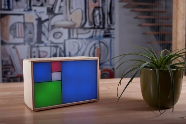
Artists have been incorporating the golden ratio in their work for many hundreds of years, and it is thought that when proportions are in line with this ratio, it tends to be more aesthetically pleasing. With that in mind, the clock that [Philippe] created must mathematically be the best looking clock we’ve ever featured, even if it is somewhat difficult to tell time from it.

The clock is made up of squares which represent the first five numbers of the Fibonacci sequence. The squares are backlit with LEDs, which will illuminate red for the hour, green for the minute, and blue representing the overlap of hours and minutes. Simply add up the red and blue squares to get the hour, and add the green and blue squares to get the minutes. The minutes are displayed in 5 minute increments since there aren’t enough blocks though, so you’ll also have to multiply. Confused yet? If not, it turns out that there are several ways to display certain times using this method, any of which can be randomly selected by the clock. [Philippe] reports that there are 16 different ways to represent 6:30, for example.

The clock is driven by an ATmega328P and is housed in a wooden case. There are schematics and code available on [Philippe]’s site if you want to build your own, there are detailed descriptions of how to tell time with this clock. You’ll probably need those. If you like getting confused by clocks, you might also like this one as well.

Continue reading “Fibonacci Clock Is Hard To Read, Looks Good”

Brewdoo Helps Keep The Office Coffee Fresh

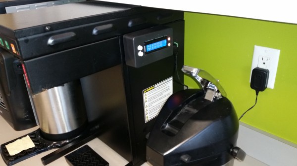
Until about lunch time, the coffee goes pretty fast in our office. Only a few of us drink it well into the afternoon, though, and it’s anyone’s guess how long the coffee’s been sitting around when we need a 4:00 pick-me-up. It would be great to install a coffee timer like [Paul]’s Brewdoo to keep track of these things.

The Brewdoo’s clean and simple design makes it easy for anyone in the office to use. [Paul]’s office has two carafes, so there’s a button, an RGB LED, and a line on the LCD for each. Once a pot is brewed, push the corresponding button and the timer is reset. The RGB LED starts at green, but turns yellow and eventually red over the course of an hour. Brewdoo has a failsafe in place, too: if a timer hasn’t been reset for four hours, its LED turns off and the LCD shows a question mark.

[Paul] knew he couldn’t touch the existing system since his company leases the equipment, so the Brewdoo lives in an enclosure that [Paul] CNC’d with custom g-code and affixed to the brewing machine with hard drive magnets. Although [Paul] designed it with an Arduino Uno for easy testing and code modification, the Brewdoo has a custom PCB with a ‘328P. The code, Fritzing diagram and Eagle files are up at [Paul]’s GitHub.

The Dan64: A Minimal Hardware AVR Microcomputer

[Juan] sent us his writeup of a microcomputer he built using an Arduino UNO (AVR ATmega328p) and some off-board SRAM. This one’s truly minimalistic.

Have a look at the schematics (PDF). There’s an Arduino, the SPI SRAM, some transistors for TV video output, and a PS/2 connector for the keyboard. That’s it, really. It’s easily built on a breadboard in a few minutes if you have the parts on hand. Flash the Dan64 operating system and virtual machine into the AVR and you’re good to go.

Now we’ve seen a few 6502-based retro computers around here lately that use a 6502 paired with a microcontroller for the interfacing, but they’ve all been bulky three-chip affairs. [Juan] wins the minimalism prize by using a 6502 virtual machine implemented in the AVR to reduce the parts count down to two chips for the whole shooting match.

Using a 6502 virtual machine was a crucial choice in the design, because there are 6502 cross compilers that will let you compile and debug code for the microcomputer on your macrocomputer and then load it into the micro to run. This makes developing for the micro less painful.

How does it load programs you ask? The old-fashioned way of course, using audio files. Although rather than using the Kansas City Standard as in days of yore, he encodes the data in short and long pulses of square waves. This might be less reliable, but it sure saves on external hardware.

Continue reading “The Dan64: A Minimal Hardware AVR Microcomputer”

Tetris on your wrist!

Ardubracelet Lets You Play Tetris On Your Wrist!

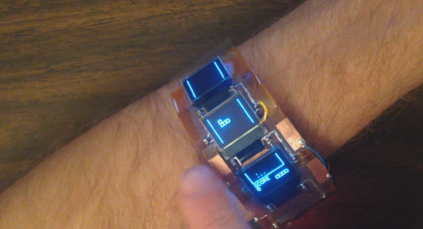
Making your own Tetris game is almost a rite of passage for hackers — [Kevin] has stepped up the game a little by making this awesome-flexible-triple-displayed-Tetris-watch dubbed the Ardubracelet.

At the recent Maker Faire SF our head editor [Mike] got a chance to meet with [Kevin] from Arduboy who told us about some of his upcoming projects — this wearable was one of them!

It features three super bright OLED screens on a flexible circuit board with conductive touch buttons to continue with the minimalist design. Instead of a wrist strap he’s actually made the ends magnetic to hold it in place — did we mention the battery also lasts for over 10 hours?

At the heart of the flexible circuit board is an Atmega328p, which is the same chip used in the Arduboy (a credit card sized GameBoy). This is just the first prototype but he’s planning on making it even better in the future complete with Bluetooth and some 3D printed parts to make it look a bit nicer.

Continue reading “Ardubracelet Lets You Play Tetris On Your Wrist!”

Public Transportation Display

display_cropped

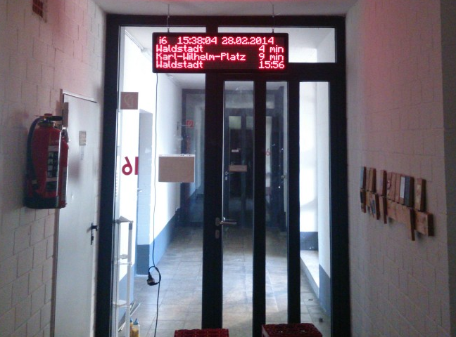
[Adrian] and [Obelix] wanted to have an easy way to know when to expect the public transportation, so they hacked an LED dot matrix display to show arrival times for stops near their dorm.

They found the display on Ebay with a defective controller which they replaced with an ATmega328p. They connected the display to the internet by adding a small TP-Link MR3020 router and connecting it to the ATmega328p via a serial line. Their local transportation office’s web page is polled to gather wait times for the stops of interest. All rendering of the final image to display to the dot matrix display is done on their PC, which then gets pushed through to the MR3020, which in turn pushes it out to the ATmega328p for final display.

[Adrian] and [Obelix] warn about setting proper watchdog timers on the display driver to make sure bugs in the controller don’t fry the dot matrix elements. Their ATmega328p dot matrix driver code can be found on [Adrian]’s GitHub page.

Check out a video of the display in action after the jump.

Continue reading “Public Transportation Display”

Artemis Synthesizer Kit

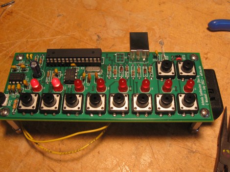
The Artemis Synthesizer was created as a kit for Boston University’s Artemis Project. This project aims to teach female rising high school freshmen about computer science with hands-on activities. [Chris] based the kit on a ATMEGA328P microcontroller and a MCP4921 digital to analog converter. It can be used in a keyboard mode, where the buttons toggle various notes of the scale, or in a sequencer mode, where the buttons are used to toggle pre-programmed sequences.

[Chris] wanted the kit to be usable by the students after the workshop, so he used an optical link dubbed the “Optoloader” to program new sequences and waveforms into the device. A web based application allows for waveforms and sequences to be built in the browser, then programmed by holding a phototransistor up to a blinking square. The square flashes black and white corresponding to a Biphase Mark Code encoded message. This is decoded by the microcontroller on the synthesizer and stored in memory. As a result, no special hardware is needed to play new waveforms and sequences.

[Chris] has a thorough write up for the project, including feedback surveys from the students. He plans to add more specific information about the Optoloader in the future.

Check out a video of the kit in action after the break.

Continue reading “Artemis Synthesizer Kit”

Video: Working With The 3pi Robot’s Line Sensors

This week, we are serving up part five in our series where we are using the Pololu 3pi robot as a fancy development board for the ATmega328p processor. This week we are taking a quick break from working with the perpherals specific to the processor and will show how to work with the 3pi’s line sensors. A quick look at the schematic for the 3pi might lead you to think that you should be reading the line sensors with the A2D peripheral. Even though they are wired to the A2D pins, they need to be read digitally. In the video, [Jack] will show how to read raw values from the sensors and then how to calibrate the results so that you can get a nice clean 8-bit value representing what the sensors are seeing. Of course, that would happen under normal circumstances. Murphy had his way in this video and it turned out that our studio lighting was interfering a bit with the sensor readings when we were shooting so we didn’t get as good of a calibration as we would have liked when we shot.

Video is after the break.

In case you have missed the previous videos here are some links:

Part 1: Setting up the development environment
Part 2: Basic I/O
Part 3: Pulse Width Modulation
Part 4: Analog to Digital conversion

Continue reading “Video: Working With The 3pi Robot’s Line Sensors”