AVR Boost Converter

avrboost

Over at SpriteMods, [sprite_tm] realized that a microcontroller could be used as a boost converter to power itself. A boost converter steps up voltage from a battery by switching the output of a coil. First, it is tied to ground so a magnetic field can build up in the coil. It is then released as a higher voltage than the input. Normally dedicated chips do this at an incredibly high frequency, but the PWM signal from an AVR works well enough. This can be used in low-power situations where space is an issue.

[via EMSL]

64 Synchronizing Fireflies

screenshot_007

[Alex] of tinkerlog created a set of 64 RGB fireflies that synchronize to blink all at once. We covered the kit earlier, but he has assembled a set of 64. Each firefly is independently controlled by an ATtiny13 that reads a phototransistor and lights up an RGB LED. The fireflies are programmed to blink a certain rate, but blink faster if they detect other blinks. After a few cycles, the fireflies begin to blink in unison. When the fireflies are arranged in different configurations, different patterns emerge. He is selling kits and has instructions for building your own. Videos of the fireflies after the jump.

Continue reading “64 Synchronizing Fireflies”

Controllable Bristlebot

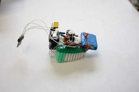
[sprite_tm], whose projects we have covered in the past, took the popular bristlebot to an extreme and created a controllable version. A bristlebot consists of a small vibrating motor mounted with a battery on the head of a toothbrush. These micro-robots buzz around randomly, and he attempted to tame them. He used a platform of twin bristlebots and added an optical sensor from a laser mouse and an ATtiny13. The optical sensor is used to determine the relative motion of the robot, so that the motors can be adjusted accordingly. He also has a video of the bot using the sensor to find a mark on the floor and stay within bounds. Although it isn’t as accurate, it acts like a traditional line-following robot.

Continue reading “Controllable Bristlebot”

Rocket Acceleration Logger

rocketdatalogger

Have you ever wondered how high or how fast a model rocket goes when you launch it? [sprite_tm] did, so he decided to build a low cost, lightweight data logger that he could fit into the nose cone of his rocket. To keep the circuit small, he built it around the popular ATtiny13 microcontroller. The microcontroller collects data from a Freescale MMA7260, a 3-axis accelerometer that he extracted from a third-party Wii nunchuck controller. After the microcontroller collects the data, it’s stored in 32K of EEPROM on a 24C256. All of this is powered by a small 3.6v Li-ion battery, which is the largest part of the circuit. If this sounds like something you’d like to make, he has detailed instructions along with the software used available on his site. While we don’t launch a lot of model rockets here, we may soon start just so that we have an excuse to build this.

ATtiny Breadboard Headers

attiny

[Alex] was frustrated by the amount of time it took to start prototyping with an AVR ATtiny. To make things easier, he built headers that carry the 8 and 20 pin chips and plug directly into breadboards. The boards include a 6pin ISP header, resonator, pull-up resistor, reset, and blocking caps. The ATtiny2313 version also has a serial connection header. This is a prototype though, and he forgot to route one of the connections. He plans on having a large batch of boards ready for next month.

Minimalist LED Light Detecting Candle

[youtube=http://www.youtube.com/watch?v=sPe5RtUOOdc]

Our flickering LED circuit combined two known circuit, and certainly wasn’t graceful because of it. [sprite_tm] saw quite a few areas where the circuit could be reduced. He ended up taking it down to just two LEDs, a battery, and an ATtiny13. The first step was getting rid of the current limiting resistors. The datasheet shows that with a 3V supply the AVR will limit the current well below the maximum current. The light sensor was removed next. [sprite_tm] referenced an earlier post on sensing with LEDs. He measures the voltage across one of the LEDs while it is off to see how much light is hitting it. The current draw while on is 10mA and 50uA while off.

Flickering LED Circuit

Here’s a simple project for your Halloween celebration. The other day while looking through our box of Halloween decorations, we noticed that the incandescent lamp in one of the jack-o’-lanterns was burnt out. Instead of simply replacing the outdated bulb, we decided to build a small dark detecting circuit with 2 yellow LEDs based on this Evil Mad Scientist Laboratories design. After successfully building the circuit, we took the project one step further by incorporating an Atmel ATtiny13 microcontroller. The code switches the LEDs on and off randomly for a flickering effect and is based on this instructable. Below is the schematic we created in EAGLE and a parts list.

Continue reading “Flickering LED Circuit”