JTAG Dongle Pushes Code To FPGA After Bootup

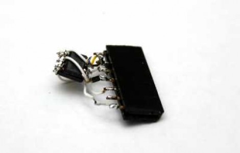
This gnarly beast has near-magical qualities. [Sprite_TM] patched it together as a dongle which attaches to a JTAG header (we’re fairly certain this is not a standard footprint for that interface though). He uses it to push code to an FPGA after that device boots. Why? Well, there’s several reason, but the most generic answer is that some boards will not boot unless there is a chain of trust that validates the code which will be running.

In this case, [Sprite_TM] is using a knock-off board he acquired from a Chinese supplier. It’s a hardware network terminal (thin client), and as you can see in the video after the break, it works just fine. But that’s pretty boring and he wanted to use it for his own purposes. When he plugs in the dongle and powers up the board the network terminal is nowhere to be found, replaced with the code to play Pac-Man as if were a full arcade cabinet.

The dongle is simply a female DIL header, an ATtiny85, and a flash memory chip. The AVR has a software UART that speaks XSVF, the protocol used to push data to the FPGA. The data to be written is stored in the memory chip, and with that header in place reprogramming the AVR is just a matter of connecting an ISP programmer. Brilliant!

Continue reading “JTAG Dongle Pushes Code To FPGA After Bootup”

Learning To Use The V-USB (AVR USB Firmware) Library

The V-USB library is a pretty handy piece of code that lets you add USB connectivity to ATtiny microcontrollers (it was previously named tinyUSB). But if you’ve ever looked into adding the library to your own projects you may have been stymied by the complexity of the code. There are many examples, but there’s a lack of a concise quick-start for the uninitiated. [Joonas Pihlajamaa] has been working to correct that shortfall with his four-part V-USB tutorial series. It’s not for the absolute newbie; you should already be comfortable working with AVR chips but that’s the only real prerequisite we can see.

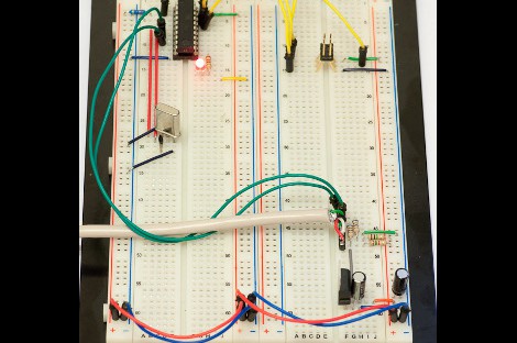
He starts the series with a look into the hardware considerations. USB provides a 5V power rail but the data lines expect 3.3V logic so this must be accounted for. With the test rig built on a breadboard he moves on to pick apart the code, covering various user-defined variables that you’ll need to set based on your project’s needs. We’re going to keep this on the back burner and hopefully the Troll Sniffing Rat will get a makeover (although we must say comments have been a lot nicer as of late… keep it up!).

We’ve embedded links to all four tutorial parts after the break.

Continue reading “Learning To Use The V-USB (AVR USB Firmware) Library”

Build Your Own 4-channel Logic Analyzer

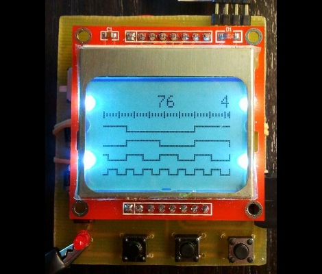
If you’re just getting into hobby electronics chances are there are lots of tools you’d like to get you hands on but can’t yet justify the purchases. Why not build some of the simpler ones? Here’s a great example of a 4-channel logic analyzer that can be your next project and will add to your arsenal for future endeavors.

As you can see, [Vassilis’] creation uses a cellphone-sized LCD screen as the output. It is powered by four rechargeable batteries and driven by an ATmega8 microcontroller. He’s designed the tool without power regulation, relying on the ATmega’s rather wide range of operating voltages, and a few diodes to step down that voltage for the LCD screen.

As you can see in the clip after the break, alligator leads can be used to connect the test circuit to the inputs (don’t forget the ground reference!). Thee buttons at the bottom let you navigate the captured data by panning and zooming. Perhaps the best design feature is the single-sided circuit board which should be quite easy to reproduce at home.

Continue reading “Build Your Own 4-channel Logic Analyzer”

Numerous Quiz Buttons Built On The Cheap

[Sprite_TM] was tapped to build a rather large quiz buzzer system. Judging from his past work we’re not surprised that he seemed to have no trouble fulfilling the request. As the system is not likely to be used again (or rarely if it is) he found a way to finish the project that was both quick and inexpensive.

Each buzzer consists of a base, a button (both mechanical and electrical), and a couple of LEDs to indicate who buzzed in first. The mechanical part of the button uses a plastic bowl from Ikea and a wooden dowel surrounded by some pipe insulation. A momentary push switch is glued on the top of that dowel, and the insulation projects above that just a bit. This way it acts as a spring. The Dowel has been sized so that the bowl lip will hit the wooden base just as it clicks the switch.

As you can see, all of the buzzers are interlinked using Ethernet cable. The real trick here is how to read 14 buttons using just one CAT5 cable. This is done with the clever use of a 4×4 button matrix for a total of 16 buttons. The matrix also includes the LEDs for each buzzer. Since CAT5 has four twisted pairs this works out perfectly.

Looking for a more robust system thank this? Here’s a pretty nice one.

AVR External Memory Interface (XMEM) Reads Input Matrix

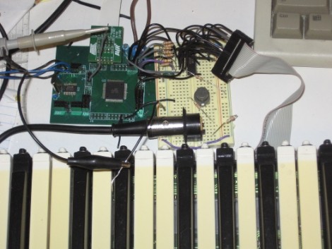
Reading from a large number of inputs, like this piano keyboard, can be tedious. Even when multiplexing there’s a lot to keep track of. But if you choose the right microcontroller, you may have hardware assistance. Here’s an ATmega640 is using it’s external memory interface to read the key matrix.

You may remember the Open Music Labs article about reading from a shift register using just one pin of a microcontroller. This time around a shift register is still used, but instead of pulling in a long line of parallel inputs, the switches are multiplexed to reduce the number of I/O pins used to read them.

A 74HC573 is used to facilitate the multiplexing. We won’t go into how that part is accomplished; there’s a separate post that explains the process. What’s unique here is that the XMEM peripheral of the AVR microcontroller is used to grab the data. This is intended for external memory chips, but if you get the timing just right, it greatly simplifies reading in a matrix of up to 128 inputs.

Pushing FPGA Config Files Via Serial Using ‘cat’

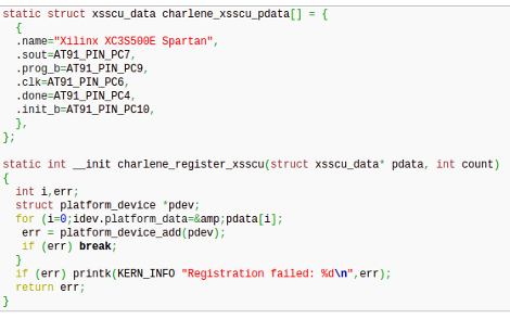
[Andrew] is trying to buckle down and hammer out his PhD project but was surprised by the sorry state of the configuration options for his FPGA/ARM dev board. Using JTAG was painfully slow, so he studied the datasheet to see if there was another way. It turns out the Xilinx FPGA he’s using does have a slave serial mode so he came up with a way to push configuration from the ARM to the FPGA serially.

Four of the connects he needed were already mapped to PortC pins on the AT91SAM9260 ARM System on a Chip. He ended up using the EN_GSM pin on the FPGA, since there is no GSM module on this board; connecting it to the microcontroller with a piece of wire. Now he can SSH into the ARM processor, grabbing information on the FPGA from /dev/fpga0. When it comes time to program, it’s as easy as using the cat command on the binary file and redirecting the output to the same hook.

LUFA Open Source USB Stack Now For NXP ARM Processors

Looks like the Lightweight USB Framework for AVRs (LUFA) has just been ported for ARM microcontrollers. NXP recently released a package for their LPC Cortex M3 family of ARM controllers. You won’t find a reference to LUFA on their nxpUSBlib description page (which we think is kind of sad), but if you grab a copy of the beta code the Version.h header file shows that it is indeed a port of the project. This is further backed up by the LUFA creator, [Dean Camera], who consulted with the NXP team doing the work.

The package provides an open-source USB stack that you can use in your projects as a USB host or USB device. We’re advocates of open source packages like this one as it makes it much easier for hobbyists to get help using the tools, and it allows the community to give back through bug fixes and feature additions.

We’ve highlighted a few LUFA projects, like this keyboard remapper and this AVR programmer. We’re looking to seeing the first set of NXP LUFA projects roll through!

[Thanks Johnny]