Panel-Mounted Breadboard Accessories

[Chuck Stephens] grew up with Radio Shack 100-in-1 electronic kits. The ones with lots of components and spring terminals that could be wired to be a radio, a burglar alarm, or whatever.[Chuck] graduated to solderless breadboard, but did miss having panel mounted components like pots and switches easily available. So he has been building his own accessory boxes.

Of course, it is easy enough to just connect breadboard wires to component, but [Chuck] went further than that. Using boxes of different types (including a cigar box), he mounted the components properly and also wired them to a breadboard for easy connection.
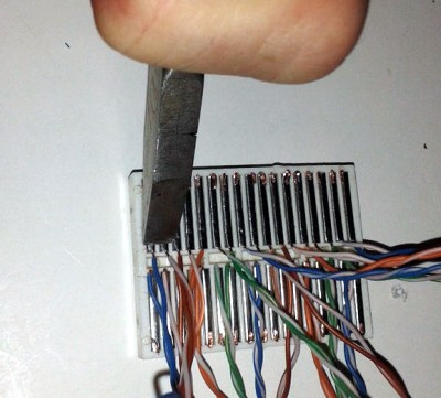
If you’ve ever tried to solder to breadboard springs (we have), you’ve found it is hard to get adhesion to the shiny metal. [Chuck] solved the problem by crimping little wire hooks to the springs. The result is a good looking and functional prototyping aid.

They do make tiny breadboard style contacts (called tie point blocks; good luck finding them) for this kind of application, but the crimp technique works on common breadboards. These are cheap and much easier to find.

Of course, these days, we are as likely to want to mount SMDs than panel mounted controls. Now if we could only figure out where to put the components. If you want something less involved, take a look at the video below.

Continue reading “Panel-Mounted Breadboard Accessories”

3D Printed Vice Holds Dev Boards Beside Breadboard

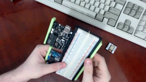
The Stickvise has been a staple of the Hackaday community for a while now. If you need something held for soldering there’s no better low-cost helping hand. But if you’re just using a breadboard and a dev board of some sort, there’s another vice on the horizon that uses similar spring clamping to hold everything in place while you build something awesome.

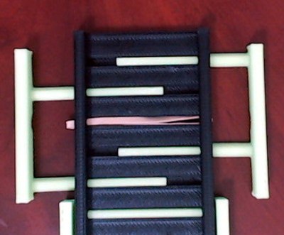
BreadboardVise1-croppedWhile [Pat]’s inspiration came from the aforementioned Stickvise, the new 3d-printed vice is just what you’ll need before you’re ready to do the soldering. The vice is spring-loaded using rubber bands. The base is sized to fit a standard breadboard in the center with clamping arms on either side to hold dev boards such as an Arduino. This innovative yet simple de”vice” grips boards well enough that you won’t be chasing them around your desk, knocking wires out of place, anymore.

There are some nuances to this board, so be sure to check out the video below to see it in action. As we mentioned, it uses rubber bands instead of springs to keep it simple, and it has some shapes that are easily 3d printed such as the triangular rails. If you want to 3d print your own, the files you’ll need are available on the project’s site. If you want to get even simpler, we’ve seen a few other vices around here as well.

The Stickvise is available for sale in the Hackaday Store.

Continue reading “3D Printed Vice Holds Dev Boards Beside Breadboard”

Vulcan 74: A Masterpiece Of Retro Engineering

[Radical Brad] has played around with FPGAs, video signals, and already has a few astonishing projects of bitbanged VGA on his resume. Now he’s gone insane. He’s documenting a build over on the 6502.org forums of a computer with Amiga-quality graphics built out of nothing but a 65C02, a few SRAM chips, and a whole pile of logic chips.

The design goals for this project are to build a video game system with circa 1980 parts and graphics a decade ahead of its time. The video output is VGA, with 400×300 resolution, in glorious eight-bit color. The only chips in this project more complex than a shift register are a single 65c02 and a few (modern) 15ns SRAMs. it’s not a build that would have been possible in the early 80s, but the only thing preventing that would be the slow RAM chips of the era.

So far, [Radical] has built a GPU entirely out of 74-series logic that reads a portion of RAM and translates that to XY positions, colors, pixels, and VGA signals. There’s support for alpha channels and multiple sprites. The plan is to add sound hardware with support for four independent digital channels and 1 Megabyte of sample memory. It’s an amazingly ambitious project, and becomes even more impressive when you realize he’s doing all of this on solderless breadboards.

[Brad] will keep updating the thread on 6502.org until he’s done or dies trying. So far, it’s looking promising. He already has a bunch of Boing balls bouncing around a display. You can check out a video of that below.

Continue reading “Vulcan 74: A Masterpiece Of Retro Engineering”

Hackaday Prize Entry: SnapVCC

While it’s the easiest way to lay out a simple circuit for prototyping, breadboards are a pain. They are the ultimate kludge; they work well enough, but no one will ever say that a solderless breadboard is the most elegant solution.

[Mahesh] isn’t completely fixing the problems of solderless breadboards, but he has come up with a better way to supply power to breadboards. It’s a project called snapVCC, and it turns a 9 volt battery into a regulated 3.3 or 5 volt supply.

The idea behind snapVCC is simple enough; just add a circuit board to the top of a nine volt and add a voltage regulator. [Mahesh] is using an LM317 adjustable regulator, with a switch to change the output voltage from 3.3 to 5 volts. An LED indicates the output active, and another switch disconnects the battery from the circuit. Yes, it’s very simple and very useful, confounding everyone who is wondering why this project didn’t already exist.

The 2015 Hackaday Prize is sponsored by:

A Stack Of Boards For An Edison Breadboard Adapter

The Intel Edison is a neat piece of hardware, but the connector for the Edison is extremely intimidating and the Mini breakout board is incompatible with breadboards. What’s [Federico], a builder of Internet of Things to do? Etch their own breakout board.

The Mini Breakout board for the Intel Edison is the official ‘minimal’ offering for getting the Edison up and running with a mess of jumper wires and LEDs. While this breakout board handles the USB to UART bridge, power regulation, and exposes all the pins on the Edison connector, it is terrible for prototyping. It’s a 4×14 array of holes on a 0.1″ grid that are hidden underneath the Edison.

[Federico] handled this problem with a copper clad board and a little bit of ferric chloride. He jumped into Eagle and created a breakout board to turn the 4×14 pin grid into a more sensible breadboard-friendly layout.

The breadboard-friendly adapter doesn’t have level shifters, but by using the mini-breakout board between the Edison and the breadboard adapter [Federico] still has the UART to USB hardware and a battery charging circuit. Still, there’s room for improvement and we can’t wait to see what he comes up with next.

Hackaday Links Column Banner

Hackaday Links: November 30, 2014

Tired of wiring up the power rails and serial adapter every time you build something on a breadboard? [Jason] has you covered. He put his Breadboard Buddy Pro up on Indiegogo, and it does everything you’d expect it to: power rails, USB to UART bridge, and a 3.3 V regulator. Oh, he’s not using an FTDI chip. Neat.

With Christmas around the corner, a lot of those cheap 3-channel RC helicopters are going to find their way into stockings. They’re cool toys, but if you want to really have fun with them, you’ll need to add a penny.

Here’s a crowdfunding campaign for a very interesting IoT module. It’s a UART to WiFi adapter that has enough free Flash and RAM to run your own code, GPIOs, SPI, and PWM functions. Wait a second. This is just an ESP8266 module. Stay classy, Indiegogo.

Mankind has sent space probes to the surface – and received pictures from – Venus, Mars, the Moon, Titan, asteroids Itokawa and Eros, and comet Comet 67P/Churyumov–Gerasimenko. In a beautiful bit of geological irony, every single one of these celestial bodies looks like a rock quarry in Wales. That quarry is now for sale.

Here’s something exceptionally interesting. It’s a browser plugin that takes a BOM, and puts all the components into a cart. Here’s the cool bit: it does it with multiple retailers. The current retailers supported are Mouser, Digikey, Farnell/Element14, Newark, and RS Components.

Want a death ray? Too bad, because it’s already been sold.

Breadboarding A 68000 Computer In Under A Week

We’ve been lurking over at Big Mess ‘o Wires as [Steve] geared up for his 68000 computer build. One of his previous posts mentioned a working breadboard version but we figured it would be a ways off. Surprise, he’s got it working and what you see above took just 6 days of “occasional work” to get running.

The chip in use is actually a 68008 but we remember reading that he does plan to migrate to a 68000 because this one lacks the memory pins to address more than 1 MB of RAM. The trick here was just to get the thing running and he made some common choices to get there. For instance, he grounded the /DTACK in much the same way [Brian Benchoff] explained in his own 68k build.

We’re not sure if his address decoding was a time saver or not. If you study [Steve’s] original planning post you’ll learn that he’s going to use programmable logic to handle the address decoding. But above he wired up 74-series logic chips to perform these functions. On the one hand you know your Hardware Description Language isn’t the problem, but did you terminate one of those wires where you ought not?

Additional tripping points include a bouncing reset pin. Looking at that we’d tell [Steve] there’s a problem with his chip, except that this was his first thought as well. He went the extra mile by building and testing a replica of the reset system. This makes our brain spin… shouldn’t the reset be among the most reliable parts of a processor?

At any rate, great work so far. We can’t wait to see where this goes and we hope that it unfolds in a way that is as exciting as watching [Quinn Dunki’s] Veronica project take shape.