When Worlds Collide: 68008 Bootstrapped By An Arduino Uno

68008-ardu

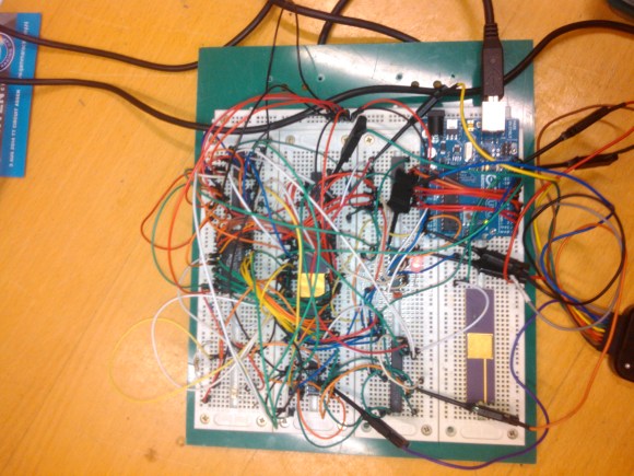
[Peter Bjornx] brings classic microprocessors and modern microcontrollers together with his Arduino bootstrapped 68008 computer. The Motorola 68008 is the 8-bit external bus version of the well-known 68000 (or 68k) microprocessor. A friend gave [Peter] one of these chips, so he built a simple computer around it.

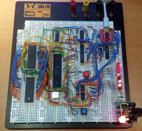
This isn’t one of those clean retrocomputers with every connection carefully planned out and wire wrapped. [Peter’s] created a true hack – a working 68k system on a breadboard created with whatever he had on hand at the time. The real gem of this system is the ROM. [Peter] replaced an EPROM chip with an Arduino.

In the not-so-good-old-days, microprocessors (and many microcontrollers) ran from an external ROM chip. This often was a UV-erasable EPROM. Carefully compiled code was burned into the EPROM with a device programmer. If the code wasn’t perfect, the EPROM had to be pulled and placed under a UV lamp for 20 minutes or so to erase it before it was time to try again. EPROM emulators were available, but they were way too expensive for the hobbyist.

Thankfully those days are far behind us now with the advent of EEPROM and then Flash. [Peter] didn’t want to revisit the past either, so he wrote a simple Arduino sketch which allowed it to act as an EPROM emulator, including address logging via the serial port.

The design still caused [Peter] some headaches, though. His major problem was a classic 68k issue, /DTACK timing. /DTACK or Data Transfer Acknowledge is one of several bus control signals used by the 68k. When the 68k performs a read from the data bus, it waits for /DTACK before it transfers data. The Arduino was too slow to release /DTACK in this case, which caused the 68k to think every read was immediately completed. There is a much clearer explanation of the 68k bus cycles on this Big Mess O Wires page. [Peter’s] solution was simple – a D flip-flop connected to the address strobe took care of the timing issues.

It took quite a bit of tinkering, but the system eventually worked. Peter was able to run the 68008 from its reset vector into a simple loop using the Arduino. It’s only fitting that the 68k program loaded by the Arduino was an LED blinker, everyone’s favorite hardware Hello World.

Thanks [Robert!]

Using Surface Mount Devices On A Breadboard

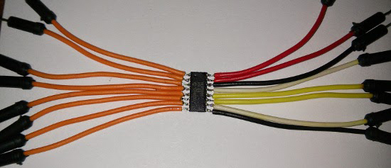
[Czar] was working on a project with the Raspberry Pi using the MCP3008 analog to digital converter. The surface mount SOIC version of this chip was slightly cheaper, and there’s always a way to make that work (Portuguese, Google Translation). How [Czar] did it is fairly impressive, as it’s a bit more flexible for breadboard designs than a through-hole version, and done correctly, is an extremely sturdy hack.

A few new leads needed to be soldered onto the SOIC package, and for this [Czar] chose jumper wires. This makes each pin easy to plug into a solderless breadboard, and since [Czar] was extremely clever, all the wires for power, ground, analog, and SPI are color coded.

Simply soldering a few jumper wires onto a chip won’t last for very long. To solve this problem, [Czar] potted the entire chip and its connections with hot glue. Probably not the best solution, and a heavy-duty epoxy would have been better, but the current build is more than enough to stand up to the relatively minor abuse it will receive on the workbench.

Breadboard Friendly ARM Board Based On STM32F4

breadboard-friendly-stm32-dev-board

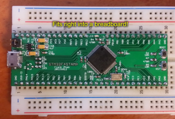
Umm yeah… this is more like it. The STM32F4Stamp is a project which [Frank Zhao] put together to make his ARM prototyping process more like is was back when everything came in a DIP format. As you can see, it’s just narrow enough to leave one row open on the breadboard for jumper wires.

Don’t get us wrong, we do really like STM’s own Discovery Boards for the hardware they deliver at a very low price. But the dual-row pin headers on the larger versions (all except the F0 variant) make it tricky to connect your peripherals. This is pushed to the point that a large percentage of hacks we’ve seen with the Discovery boards are actually just to make connecting external hardware easier.

You may be thinking that there’s a lot missing from this board, but we disagree. Obviously there’s still a USB port which can be used to power the board via a 3.3V regulator. But since the STM32 chips have a built-in bootloader the USB connection can also be used to flash firmware to the processor. Nice! It’s open hardware if you want roll your own. For your convenience we’ve embedded the schematic after the break, along with [Frank’s] demo video.

Continue reading “Breadboard Friendly ARM Board Based On STM32F4”

Breadboard Tetris Is Wire Artwork

RGB-module-breadboard-tetris

Look closely at the colored pixels on this pair of 8×8 RGB LED modules and you’ll be able to pick out some of the familiar shapes of Tetris pieces. It’s impressive that [Jianan Li] built his own color Tetris including the theme music, but look at this breadboard! The layout of his circuit is as equally impressive as the code he wrote to get the game up and running. It takes a fair amount of planning to get a circuit of this complexity to fit in the space he used, right?

There are two microcontrollers at work, each running the Arduino bootloader. The main chip is an ATmega328 which is responsible for monitoring the buttons and controlling game play. The other is an ATmega85. The eight pin chip listens to it’s bigger brother, playing the theme song when the game starts, and pausing or resuming to match the user input So is the next stop for this project playing Tetris on the side of a building?

Don’t miss the demo video after the break. We’ve also rolled in a video of his Arduino-based piano. It’s built on a breadboard that’s nearly as impressive as this. But what delights us is his skill at playing Pokemon themes on the two-octave tactile switch keyboard. Obviously those piano lessons his parents shelled out for really paid off!

Continue reading “Breadboard Tetris Is Wire Artwork”

Breadboard Sequencer Does A Lot With Very Little Hardware

breadboard-sequencer

[Jan Cumpelik] squeezes a lot of performance out of very few components with his breadboard sequencer which he calls Lunchbeat. We really like his awesome breadboard which has a series of trenches perpendicular to the bus strips framing the long sides. All of our breadboards have just one trench down the middle. This, combined with his mad breadboard skills, results in a really clean prototype.

The chip nearest his hand is the ATmega328 which drives the sequencer. It takes inputs from that row of 10k trimpots as well as a series of tactile switches. Feedback is given with the row of eight LEDs. Those are driven from a 595 shift register to save pins on the microcontroller. The remaining chip is an OpAmp which works in conjunction with a 3-bit R2R ladder DAC to output audio. Turn your speakers down just a bit before taking in the demonstration below. There you will also find an image version of his schematic that we made for your convenience. It is only available as a PDF in the code repository he posted.

Continue reading “Breadboard Sequencer Does A Lot With Very Little Hardware”

The Straddler Makes AVR Breadboarding Truly Plug And Play

the_straddler_avr_programmer

It’s not that breadboarding AVR circuits is difficult. But you have to admit that it takes some time to set everything up. We don’t label the top of our DIP chips so that you know what each pin does just by looking. Which means that wiring up the programmer involves pulling out the datasheet. [Vinnie] found the solution to this problem which is to make one of these interface PCBs for each AVR chip family. The long pins make it easy to drop over the top of your microcontroller, which is where the name comes from.

His first stab at the idea was just a hunk of home etched PCB which broke out the programming pins into the 6-pin ICSP standard. This second rendition uses the 10-pin standard and adds a few extras into the mix. He included decoupling capacitors which need to be used in every circuit anyway. There’s a crystal along with its load capacitors. This clock source is a snap to enable by burning some fuses. If you choose to use the internal oscillator instead this hardware won’t interfere. The LED is used to get you up and running with blinky firmware as quickly as possible. He plans to add jumper in the next revision which can disconnect this components from the I/O pin. Now you just need to add a 10-pin header to that USB keyboard AVR programmer and you’re in business.

Build A Bare Bones Arduino Clone Which Maximizes Its Use Of Real Estate

barebones-arduino-clone-at-home

Check out all the stuff crammed into a small swath of strip board. It’s got that characteristic look of a roll-your-own Arduino board, which is exactly what it is. [S. Erisman] shows you how to build your own copy of his YABBS; Yet Another Bare Bones Arduino (on Stripboard).

The strips of copper on the bottom of the substrate run perpendicular to the DIP chip and have been sliced in the middle. This greatly reduces the amount of jumpering that would have been necessary if using protoboard. A few wires make the necessary connections between the two tooled SIL headers that make up the chip socket. On the right hand side there a voltage regulator with smoothing caps. The left side hosts the obligatory pin 13 LED, and the crystal oscillator can be glimpsed on the far side of the ATmega328.

Pin headers along either side of the board have been altered to allow for soldering from the wrong side of the plastic frames. Note that there’s a three-pin hunk that breaks out the voltage regulator, and an ISP programming header sticking out the top to which those female jumper wires are connected.

Ringing in at as little as $2-$4.75 a piece you’ll have no problem leaving this in a project for the long hall. We can’t say the same for a $30+ brand name unit.