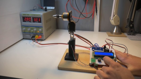
These days, brushless motors are the go-to for applications requiring high power in a compact package. It’s possible to buy motors in all manner of different configurations off the shelf, and the range available is only getting better. However, sometimes getting something truly optimal requires a bit of customization. With motors, this can involve swapping magnets or hand-winding coils. In these cases, it can be useful to test the modified motor to determine its performance. [JyeSmith]’s ESC tester is capable of just that.
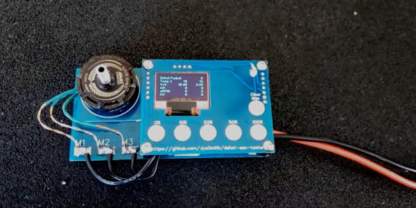
Fundamentally, the ESC tester is a simple piece of hardware. It uses a microcontroller to speak the Dshot protocol. This protocol is typically used to communicate between multi-rotor flight controllers and ESCs. In this case, the Dshot telemetry is instead displayed on a small OLED screen. This enables the user to read off KV values, as well as other useful data such as current draw and RPM. This can help quantify the effects of any modifications made to a motor, as well as prove useful for learning about parts of spurious origins.
It’s a device that should prove useful to those trying to eke out every last drop of performance from their multi-rotor builds. We expect to see more similar projects emerge as drone racing continues to increase in popularity. If you’re still trying to learn the theory behind the technology, you can always build your own brushless motor. Video after the break.
[Thanks to Keegan for the tip!]
Continue reading “Testing Brushless Motors With A Little Help From The ESC”