Edgytokei

Edgytokei’s Incredible Mechanism Shows Time Without A Face

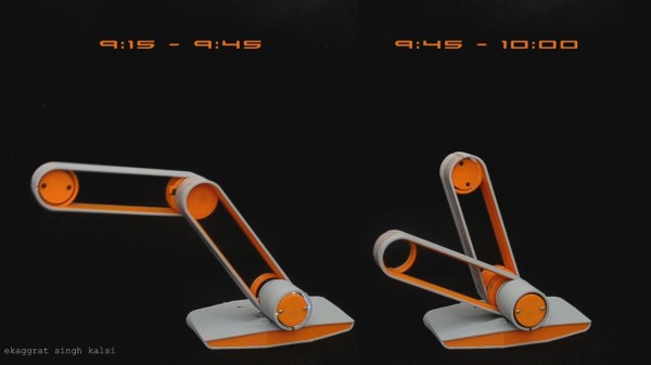
Taking inspiration from Japanese nunchucks, [ekaggrat singh kalsi] came up with a brilliant clock that tells time using only hour and minute hands, and of course a base for them to sit on. The hands at certain parts of the hour seem to float in the air, or as he puts it, to sit on their edges, hence the name, the Edgytokei, translating as “edge clock”.

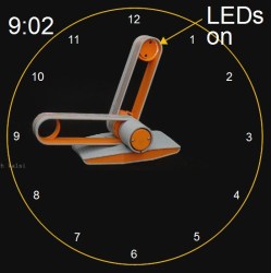
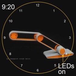
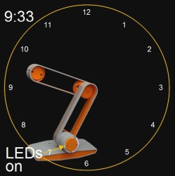
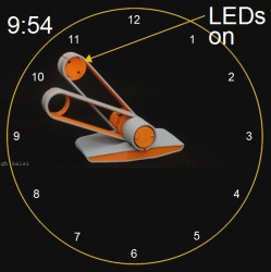
The time is a little difficult to read at first unless you’ve drawn in a clock face with numbers as we’ve done here. 9:02 and 9:54 are simple enough, but 9:20 and 9:33 can be difficult to translate into a time at first glance. Since both hands have to be the same length for the mechanism to work, how do you tell the two hands apart? [ekaggrat] included a ring of LEDs in the hub at the base and another at the end of one of the hands. Whichever ring of LEDs is turned on, indicates the tip of the minute hand. But the best way to get an idea of how it works is to watch it action in the video below.

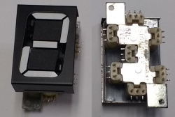
We have to admire the simplicity and cleanliness of his implementation. The elbow and the hub at the base each hide a stepper motor with attached gear. Gear tracks lining the interior of the hands’ interact with the motor gears to move the hands. And to keep things clean, power is transferred using copper tape lining the exteriors.

On the Hackaday.io page [ekaggrat] talks about how difficult it was to come up with the algorithms and especially the code for homing the hands to the 12:00 position, given that homing can be initiated while the hands can be in any orientation. The hand positions are encoded in G-code, and a borrowed G-code parser running on an Arduino Nano in the base controls it all.

Continue reading “Edgytokei’s Incredible Mechanism Shows Time Without A Face”

Celebrate Display Diversity For A Circuit Circus Clock

There’s a lot to be said for nice, tidy projects where everything lines up and looks pretty. Seeing straight lines and pleasing proportions speaks to our obsessive-compulsive tendencies, and tends to soothe the mind and calm the spirit. But disorder is not without its charm, and mixing it up a little from time to time, such as with this mixed-media digital clock, can be a good idea.

Now, we know what you’re thinking — yet another Nixie clock. True, but that’s only half the story — or more accurately, one-sixth. There’s but a single Nixie in [Fuselage]’s circus-punk themed clock, used for the least significant digit in the hours part of the display. The other digits are displayed with four seven-segment devices — a Numitron, a vacuum fluorescent display, and an LED dot display — plus a real oddball, an old electromechanical display with individual slides for each character and a rear-screen projector. The RTC part of the project is standard Arduino fare, but as you can imagine the power supply needed for such a diversity of displays is pretty complex and has to provide everything from +5 to -270 volts. Each display needs its own driver, too, making this more of a zoo than a circus. The mixed up look just works with the circus theme, too. We’d really like more information on the projector display, though.

Looking for a real statement for your next clock build? Check out the rare as hens’ teeth NIMO tube.

Continue reading “Celebrate Display Diversity For A Circuit Circus Clock”

Have Your Own 200 Water Street Digital Clock

On the front of a building in New York City, above a branch of the ubiquitous Starbucks coffee chain, there is a clock. It is no ordinary clock, the 200 Water Street clock is an art installation created by the artist [Rudolph de Harak], and consists of 72 lighted numbers which are illuminated in sequence to show hours, minutes, and seconds. It is a landmark of sufficient fame that [Jason Ben Nathan] and [Eldar Slobodyan], Cornell University students of [Bruce Land], decided to make their own tribute to it as their course project.

Water Street clock at night
Water Street clock at night [via NYC ♥ NYC]
It’s a fairly straightforward build, thanks to the use of Adafruit Dotstar multicolour LED strips which are populated with APA102 pixels. Behind the scenes is a PIC32 microcontroller, and the time information comes from an off-the-shelf 60kHz WWVB time signal receiver. There is also a temperature sensor, for a handy second function.

The front panel is a piece of ply with the required numbers nicely laser-cut. All the schematics and code are available, should you fancy your hand at building your own version of the clock.

If you are curious about the real-life clock here’s an image. But you get a much more interesting perspective if you stand in front of it. If you just can’t go there, get an approximation through the wonders of Google Street View.

Seven-Segment Flip Clock Display Finally Finished

Earlier this year, we mentioned in a Hackaday Links article that [Spencer Hamblin] was in the process of building a seven-segment flip clock. Well, it’s finally finished, and it looks great!

Vintage seven segment digits make up the display. These digits work the same way that flip-dot displays work – current through each segment’s coil creates a magnetic field which causes the segment to flip over. Current in the other direction creates the opposite magnetic field and flips the segment the other way. On these digits, there are three connections on the coils. The middle one is power and the other two are used to enable and disable the segment – ie., flip it one way or the other. To save on pins on the microcontroller, [Spencer] connected all the middle coil pins together on a digit. Each coil can be powered using a single pin on the microcontroller. Similarly, the segments for each digit are connected together as well, so one pin on the micro controls the same segment on each of the digits. The microcontroller in question is the AVR ATMega48.

There are two parts of the clock face left to do: AM/PM and whether the alarm is set or not. [Spencer] used a fifth digit, slightly offset, for those – the top and middle segments are used.

For the housing of the clock, [Spencer] used layers of offsetting colored wood. The wood (sapele and ash) were CNC cut and aligned. The back plate, also made from wood, holds buttons for setting the time and alarm, as well as some LEDs for what [Spencer] calls the “daylight alarm.” A capacitive sensor on the top of the unit (inside the wooden case) is used to turn the alarm off.

The result, after sanding and shellacing, looks amazing. [Spencer] nailed the art-deco look he was going for. There are plenty of pictures and the circuit designs, schematics and code are on [Spencer]’s Hackaday.io page, and you can find the Hackaday links post here. This is a complete log of a project we mentioned earlier on Hackaday, here, but there are other mechanical flip display clock projects, such as this DIY mechanical flip seven-segment prototype, or, you could create your own (really big) clock using this Lego mechanical seven-segment display.

via Reddit.

Color Changing Clock Uses PCB Digits

There’s an old saying, that you should do everything at least twice. Once to learn how to do it, and then a second time to do it right. Perhaps [Zweben] would agree, since he wasn’t satisfied with his first Neopixel clock and proceeded to build another one. One lesson learned: soldering 180 tiny solder joints isn’t much fun. This time, [Zweben] set out to make a printed circuit board and redesign the clock to make it easier to assemble.

The clock uses multiple copies of a single circuit board. The board holds Neopixel strips in a 7-segment arrangement. Each board can also hold all of the electronics needed to drive the clock. Only the first board gets the microcontroller and other circuits.

Continue reading “Color Changing Clock Uses PCB Digits”

A Minimalist Weather Clock With A Unique Display

If you’re looking for a home hub to display weather, time, and important family information, the formula is pretty simple: build yet another “magic mirror” project. We’re not complaining — magic mirrors look great. But if all you need is time and weather, this elegant pixel display is something just a little bit different.

Among his many criteria for the perfect hack, [Dominic] lists usefulness, visual appeal, and low cost. We’ll agree that his minimalist weather clock hits all those marks, and with the careful selection of a 16 x 32-pixel RGB display module, [Dominic] ended up giving back to the community by developing an Arduino driver for it. He points out that strips of Neopixels could have been used for the display, but they’d have ended up costing more, so the LED matrix was a sensible choice. A 3D-printed separator grid and a paper diffuser provide the proper pixelated look, and some simple animated icons display the two-day weather forecast. We find the time and temperature numerals a little hard to read, but it’s not bad considering the limited resolution of the display. And the case is a nice bit of woodworking too. Not a bad result for only €43.

We’re intrigued by the P10 LED matrix module [Dominic] used for this one. It might be a good choice for a word clock and weather station, or with his driver, a display for just about anything.

Over-Engineered Clock Uses No Less Than Five ESP32s

When [Proto G] enters into an Instructables contest whose only requirement is for the project to be wireless; he does so with style. Let’s put aside for a minute that he’s using a separate ESP32 board for each of the clock’s characters – that’s one for the hour, then one for the colon, one for the minutes and other colon and then the seconds. If you’re keeping count, that’s FIVE ESP32s. But like we said… put that aside and take into account that he’s using three different wireless communication protocols to make the five ESP32s get cozy with one another:

  1. His phone is connected to a cell tower.
  2. One of the ESP is connected to his phone to get the time.
  3. Two other ESPs connect to his phone and send minutes and seconds info to two more ESPs via the board’s internal communication protocol – ESPNOW

In case you’re wondering; the boards he’s using each have an OLED, battery, USB-to-serial converter and of course the ESP32. [Proto G] felt he could add some more complication to his project by crushing the programming connector on one of the boards with his chair. He had to break out the soldering iron and some jumper wire to make a quick but effective repair.

Be sure to check out his Instructables page for more great projects!