
If you have a CNC router, you know you can engrave just about any text with the right tool, but Jointly is a typeface that isn’t meant to be engraved. That would be too easy for [CobyUnger]. His typeface “Jointly” is the first we’ve seen that’s meant to be used as joinery.
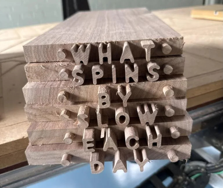 The idea is simple: carve mortises that take the shape of letters in one piece, and carve matching letter-tenons into the end of another. Push them together, and voila: a joint! To get this concept to work reliably, the font did have to be specially designed — both the inner and outer contours need to be accessible to a rotary cutting tool. Cutting tools get harder to use the smaller they go (or more fragile, at any rate) so with Jointly, the design spec was that any letters over 3/4″ (19.05 mm) tall needed to be handled with a 1/8″ (3.175 mm) rotary cutter.
This gives the font a friendly curved appearance we find quite fetching. Of course if you’re going to be cutting tenons into the end of a board, you’re going to need either some serious z-depth or an interesting jig to get the end of the board under the cutting head. It looks like [CobyUnger] has both, but he mentions the possibility of using a handheld CNC router as the cheaper option.
Speaking of routing out type, do you know the story of Gorton? You can’t make joinery with that typeface, but you’ve almost certainly seen it.


