Measuring Tiny Current With High Resolution

measuring-microamps-at-3MHz

[Paul] knew that he could get an oscilloscope that would measure the microamp signals with the kind of resolution he was after, but it would cost him a bundle. But he has some idea of how that high-end equipment does things, and so he just built this circuit to feed precision data to his own bench equipment.

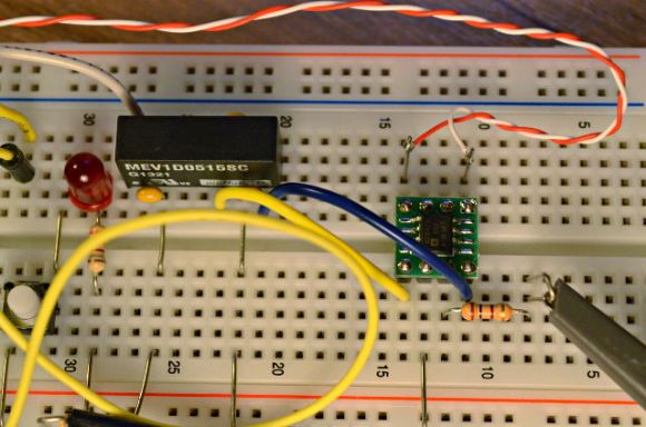
He’s trying to visualize what’s going on with the current draw of a microcontroller at various points in its operation. He figures 5 mA at 2.5 mV is in the ballpark of what he’s probing. Measurements this small have problems with noise. The solution is the chip on the green breakout board. It’s not exactly priced to move, costing about $20 in single quantity. But when paired with a quality power supply it gets the job done. The AD8428 is an ultra-low-noise amplifier which has way more than the accuracy he needs and outputs a bandwidth of 3.5 MHz. Now the cost seems worth it.

The oscilloscope screenshot in [Paul’s] post is really impressive. Using two 1 Ohm resistors in parallel on the microcontroller’s power line he’s able to monitor the chip in slow startup mode. It begins at 120 microamps and the graph captures the point at which the oscillator starts running and when the system clock is connected to it.

Current Limiter For A MOT Welder

current-limiter-for-MOT-welder

[Mike Worth] wanted the option to run his Microwave Oven Transformer welding rig at less that full power. After being inspired by some of the other MOT hacks we’ve featured he figured there must be a lot of ways to do this. But his searches on the topic didn’t turn up anything. So he just designed and built his own adjustable current limiter for the welder.

At the beginning of his write-up he details what we would call a bootstrap procedure for the welder. Go back and check out his original build post to see that he had been holding the framework for the cores together using clamps. To make the setup more robust he needed to weld them, but this is the only welder he has access to. So he taped some wood shielding over the coils and fired it up.

The current limiter itself is built from a third MOT. Adjustment is made to the cores by changing out the E and I shaped pieces. This allows for current limiting without altering the windings. [Mike] holds it all in place with a couple of bicycle wheel quick connect skewers.

It just goes to show that you should never get rid of a microwave without pulling the transformer. Even if you don’t need a welder wouldn’t you love a high-voltage bug zapper?

Rattle Generator Is A New Type Of Dynamo For A Bicycle

rattle-generator-bicycle-spokes

This project is in one of our favorite categories; the kind where asking “why?” is the wrong question. [Berto A.] built the device after observing some power generation by placing a large magnet next to a mechanical relay coil and quickly clicking the relay’s lever. From this humble beginning he built up the RattleGen, a bicycle spoke driven generator.

To get the most power possible he searched around for a massive relay and found one which was originally meant for telephone exchanges. He cut the case open and strapped a big bar magnet to the side of the coil. Next he fabricated an arm which will press against the relay’s lever. To that he added a small wheel which is pressed each time a spoke from the bicycle passes by it. This repeated clicking of the relay lever generates a current (and a rattling sound) that is harvested by the joule thief circuit built on some protoboard. An LED is illuminated, with excess current stored in the capacitor bank. Don’t miss the build and demonstration video after the break.

Continue reading “Rattle Generator Is A New Type Of Dynamo For A Bicycle”

Whole House Current Monitoring

[youtube=http://www.youtube.com/watch?v=HlRBrTTLQFU]

[Debraj Deb] put together a current monitoring device that interfaces with the circuit box at his house. The system is controlled by a PIC 18F4520 and uses an LM358 Op-Amp to rectify the AC signal, as well as an MCP6S21 for range adjustments for detecting both high or low current loads. The data displayed on a character LCD includes average, RMS, and peak current. For now the data is saved to an EEPROM and can be dumped using a serial connection but [Debraj] plans to add a GSM modem so he can send energy use data to his cell phone.

[Thanks Ganesh]

Robot Waits For No Man When Recharging

Yikes, that power connector certainly wasn’t designed by Apple. Ugly as it may be, it’s the charging cable for a robot and acts as a sensor that allows the robot to properly align and plug into a power receptacle.

We’re going to go off on a tangent for just a second. We often think of the Rat Things from Snowcrash when considering robot power. They were nuclear powered (or something) and instead of recharging required constant cooling. Those day’s aren’t exactly around the corner but we think they’ve been realized in the lawn mowing robots that have a little nests to recharge in. Base stations work but they require the machine to return to the same place, or to have multiple charging stations.

The point is, this specialized cable makes base stations for robots obsolete. Now a robot can plug into any outlet it can get near, a great thing for robots roving large facilities. After the break you can see a video of this process. The robot arm zeros in by scanning horizontally and vertically and measuring the magnetic field put out by the AC in the wires of the outlet. Take a look, it’s a pretty neat piece of engineering.

Continue reading “Robot Waits For No Man When Recharging”

Automotive Current Monitor

If you’ve ever had a car with an electrical system problem you know how hard it can be to pin-point the source of your woes. Here’s a hackery solution that uses a diy PCB to monitor the current being drawn off of the alternator.The sensing is provided by an Allegro ACS758 integrated circuit. This chip measures current up to 150A and outputs an analog signal that can be measured by a microcontroller. In this case an AVR ATmega8 measures the signal and spits the info back to a PC via the serial port. This data can be graphed to help locate when too much current is being drawn for the battery to remain charged.

Check out that CNC milled PCB, what a beauty!

[Thanks Joshua via Elektronika]

Measuring Current Through USB

usb_current

[gmgfarrand] wanted to be able to measure the current being pulled through his USB.  He realized that even though he could just cut open the wire and measure at any point, a permanent tool for this would be quite useful.  This is a simple modification that shouldn’t take long. All you need is a spare USB cable and an enclosure. He ultimately filled his enclosure with glue to keep everything in there and solid. lets hope his soldering holds well.