How Current Shunts Work

Current. Too little of it, and you can’t get where you’re going, too much and your hardware’s on fire. In many projects, it’s desirable to know just how much current is being drawn, and even more desirable to limit it to avoid catastrophic destruction. The humble current shunt is an excellent way to do just that.

Ohm’s Law.

To understand current, it’s important to understand Ohm’s Law, which defines the relationship between current, voltage, and resistance. If we know two out of the three, we can calculate the unknown. This is the underlying principle behind the current shunt. A current flows through a resistor, and the voltage drop across the resistor is measured. If the resistance also is known, the current can be calculated with the equation I=V/R.

This simple fact can be used to great effect. As an example, consider a microcontroller used to control a DC motor with a transistor controlled by a PWM output. A known resistance is placed inline with the motor and, the voltage drop across it measured with the onboard analog-to-digital converter. With a few lines of code, it’s simple for the microcontroller to calculate the current flowing to the motor. Armed with this knowledge, code can be crafted to limit the motor current draw for such purposes as avoiding overheating the motor, or to protect the drive transistors from failure.

In fact, such strategies can be used in a wide variety of applications. In microcontroller projects you can measure as many currents as you have spare ADC channels and time. Whether you’re driving high power LEDs or trying to build protection into a power supply, current shunts are key to doing this.

Continue reading “How Current Shunts Work”

Coin Cells: The Mythical Milliamp-Hour

Just how much metaphorical juice is in a coin cell battery? It turns out that this seemingly simple question is impossible to answer — at least without a lot of additional information. The problem is that the total usable energy in a battery depends on how you try to get that energy out, and that is especially true of coin cells.

Energizer specs its 2032s at 0.2 mA

For instance, ask any manufacturer of the common 3 V lithium 2032 batteries, and they’ll tell you that it’s got 230 mAh. That figure is essentially constant across brands and across individual cells, and if you pull a constant 0.2 mA from the battery, at room temperature and pressure, you’ll get a bit more than the expected 1,150 hours before it dips below the arbitrary voltage threshold of 2.0 V. Just as it says on the tin.

What if you want to do anything else with a coin cell? Run an LED for a decade? Pull all the energy out right now and attempt to start a car? We had these sorts of extreme antics in mind when we created the Coin Cell Challenge, but even if you just want to do something mundane like run a low-power radio sensor node for more than a day, you’re going to need to learn something about the way coin cells behave in the real world. And to do that, you’re going to need to get beyond the milliamp hour rating. Let’s see how deep this rabbit hole goes.

Continue reading “Coin Cells: The Mythical Milliamp-Hour”

Current Sink Keeps The Smoke In

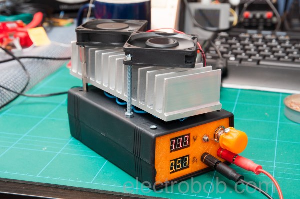
One of the most versatile tools on anyone’s work bench, at least as far as electrical projects are concerned, is a power supply. Often we build our own, but after we’ve cobbled together some banana jacks with a computer’s PSU or dead-bug soldered a LM317 voltage regulator to a wall wart, how will that power supply perform? Since it’s not desirable to use a power supply that’ll let the smoke out of everything it powers (or itself, for that matter) a constant current sink, or load, can help determine the operating limits of the power supply.

[electrobob] built this particular current sink from parts he had lying around. The theory of a constant current sink is relatively straightforward so it’s easily possible to build one from parts out of the junk drawer, provided you can find a few transistors, fuses, an op amp, and some heat sinks. The full set of schematics that [electrobob] designed can be found on his main project page. He’s also gone a step further with this build as well, since he shorted out his first prototype and destroyed some of the transistors. But, using a few extra transistors in his design also improves the safety and performance of the load, so it’s a win-win.

This constant current load also has the added feature of being able to interface with a waveform generator (an Analog Discovery, specifically) and as a result can connect and disconnect the load quickly. If you aren’t in need of an industrial-grade constant current sink and you have some spare parts lying around, this would be a great one to have around the work bench.

Hacking On The Weirdest ESP Module

Sometimes I see a component that’s bizarre enough that I buy it just to see if I can actually do something with it. That’s the case with today’s example, the ESP-14. At first glance, you’d ask yourself what AI Thinker, the maker of many of the more popular ESP8266 modules, was thinking.

The ESP-14 takes the phenomenally powerful ESP8266 chip and buries it underneath one of the cheapest microcontrollers around: the 8-bit STM8S003 “value line” chip. Almost all of the pins of the ESP chip are locked inside the RF cage’s metal tomb — only the power, bootloader, and serial TX/RX pins see the light of day, and the TX/RX pins are shared with the STM8S. The rest of the module’s pins are dedicated to the STM8S. Slaving the ESP8266 to an STM8S is like taking a Ferrari and wrapping it inside a VW Beetle.

I had never touched an STM8 chip before, and just wanted to see what I could do with this strange beast. In the end, ironically, I ended up doing something that wouldn’t be too far out of place on Alibaba, but with a few very Hackaday twists: a monitor for our washer and dryer that reports power usage over MQTT, programmed in Forth with a transparent WiFi serial bridge into the chip for interactive debugging without schlepping down into the basement. Everything’s open, tweakable, and the Forth implementation for the STM8S was even developed here on Hackaday.io.

It’s a weird project for the weirdest of ESP modules. I thought I’d walk you through it and see if it sparks you to come up with any alternative uses for the ESP8266-and-STM8S odd couple that is the ESP-14.

Continue reading “Hacking On The Weirdest ESP Module”

High Voltage Please, But Don’t Forget The Current

In high voltage applications involving tens of thousands of volts, too often people think about the high voltage needed but don’t consider the current. This is especially so when part of the circuit that the charge travels through is an air gap, and the charge is in the form of ions. That’s a far cry from electrons flowing in copper wire or moving through resistors.

Consider the lifter. The lifter is a fun, lightweight flying machine. It consists of a thin wire and an aluminum foil skirt separated by an air gap. Apply 25kV volts across that air gap and it lifts into the air.

So you’d think that the small handheld Van de Graaff generator pictured below, that’s capable of 80kV, could power the lifter. However, like many high voltage applications, the lifter works by ionizing air, in this case ionizing air surrounding the thin wire resulting in a bluish corona. That sets off a chain of events that produces a downward flowing jet of air, commonly called ion wind, lifting the lifter upward.

Continue reading “High Voltage Please, But Don’t Forget The Current”

Sciencing DVD-RW Laser Diodes

If you’ve played around with laser diodes that you’ve scavenged from old equipment, you know that it can be a hit-or-miss proposition. (And if you haven’t, what are you waiting for?) Besides the real risk of killing the diode on extraction by either overheating it or zapping it with static electricity, there’s always the question of how much current to put into the thing.

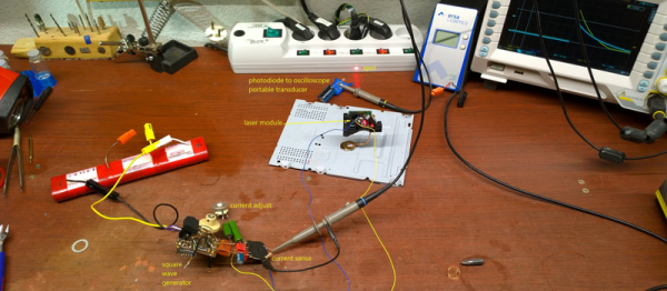
[DeepSOIC] decided to answer the latter question — with science! — for a DVD-burner laser that he’s got. His apparatus is both low-tech and absolutely brilliant, and it looks like he’s getting good data. So let’s have a peek.

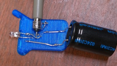
Laser Detector on 3D Printer Scrap

First up is the detector, which is nothing more than a photodiode, 100k ohm load resistor, and a big capacitor for a power supply. We’d use a coin-cell battery, but given how low the discharge currents are, the cap makes a great rechargeable alternative. The output of the photo diode goes straight into the scope probe.

He then points the photodiode at the laser spot (on a keyboard?) and pulses the laser by charging up a capacitor and discharging it through the laser and a resistor to limit total current. The instantaneous current through the laser diode is also measured on the scope. Plotting both the current drawn and the measured brightness from the photodiode gives him an L/I curve — “lumens” versus current.

laser_curve

Look on the curve for where it stops being a straight line, slightly before the wiggles set in. That’s about the maximum continuous operating current. It’s good practice to de-rate that to 90% just to be on the safe side. Here it looks like the maximum current is 280 mA, so you probably shouldn’t run above 250 mA for a long time. If the diode’s body gets hot, heatsink it.

If you want to know everything about lasers in general, and diode lasers in particular, you can’t beat Sam’s Laser FAQ. We love [DeepSOIC]’s testing rig, though, and would love to see the schematic of his test driver. We’ve used “Sam’s Laser Diode Test Supply 1” for years, and we love it, but a pulsed laser tester would be a cool addition to the lab.

What to do with your junk DVD-ROM laser? Use the other leftover parts to make a CNC engraver? But we don’t need to tell you what to do with lasers. Just don’t look into the beam with your remaining good eye!

Fail Of The Week: Inaugural Edition

We’re sure you’ve all been waiting on the edge of your seats to see whose project makes it as the first Hackaday Fail of the Week. Wait no longer, it’s [Mobile Will] with his woeful tale about monitoring AC current usage.

He had been working on a microcontroller actuated mains outlet project and wanted an accurate way to measure the AC current being used by the device connected to it. The ADE7753 energy metering IC was perfect for this so he designed the board above and ordered it up from OSH Park. After populating the components he hooked it up to his Arduino for a test run, and poof! Magic blue smoke arose from the board. As you’ve probably guessed — this also fried the Arduino, actually melting the plastic housing of the jumper wire that carried the rampant current. Thanks to the designers of the USB portion of his motherboard he didn’t lose the computer to as the current protection kicked in, requiring a reboot to reset it.

We can’t wait to hear the conversation in the comments. But as this is our first FotW post we’d like to remind you: [Mobile Will] already knows he screwed up, so no ripping on his skills or other non-productive dibble. Let’s keep this conversation productive, like what caused this? He still isn’t completely sure and that would be useful information for designing future iterations. Update: here’s the schematic and board artwork.

We’ve got a bit more to share in this post so keep reading after the break.

Continue reading “Fail Of The Week: Inaugural Edition”