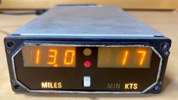
Tiny Tapout is an interesting project, leveraging the power of cloud computing and collaborative purchasing to make the mysterious art of IC design more accessible for hardware hackers. [Yeo Kheng Meng] is one such hacker, and they have produced their very first custom IC for use with their retrocomputing efforts. As they lament, they left it a little late for the shuttle run submission deadline, so they came up with a very simple project with the equivalent behaviour of the Covox Speech Thing, which is just a basic R-2R ladder DAC hanging from a PC parallel port.
The plan was to capture an 8-bit input bus and compare it against a free-running counter. If the input value is larger than the counter, the output goes high; otherwise, it goes low. This produces a PWM waveform representing the input value. Following the digital output with an RC low-pass filter will generate an analogue representation. It’s all very simple stuff. A few details to contend with are specific to Tiny Tapout, such as taking note of the enable and global resets. These are passed down from the chip-level wrapper to indicate when your design has control of the physical IOs and is selected for operation. [Yeo] noticed that the GitHub post-synthesis simulation failed due to not taking note of the reset condition and initialising those pesky flip-flops.
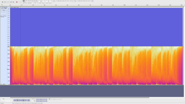
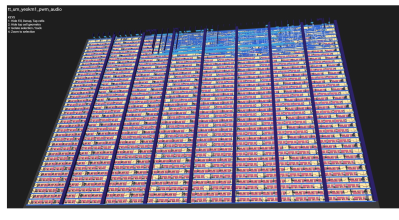
After throwing the design down onto a Mimas A7 Artix 7 FPGA board for a quick test, data sent from a parallel port-connected PC popped out as a PWM waveform as expected, and some test audio could be played. Whilst it may be true that you don’t have to prototype on an FPGA, and some would argue that it’s a lot of extra effort for many cases, without a good quality graphical simulation and robust testbench, you’re practically working blind. And that’s not how working chips get made.
If you want to read into Tiny Tapeout some more, then we’ve a quick guide for that. Or, perhaps hear it direct from the team instead?
Continue reading “Tiny Tapeout 4: A PWM Clone Of Covox Speech Thing”