POV Display Does It On The Cheap

lowBudgetPOV

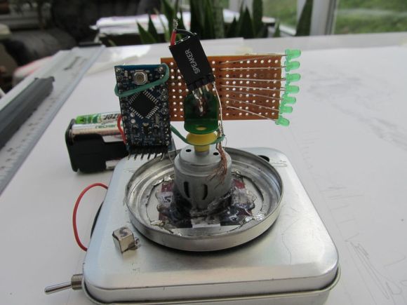
[Sholto] hacked together this ultra low-budget spinning display. He calls it a zoetrope, but we think it’s actually an LED based Persistence Of Vision (POV) affair. We’ve seen plenty of POV devices in the past, but this one proves that a hack doesn’t have to be expensive or pretty to work!

The major parts of the POV display were things that [Sholto] had lying around. A couple of candy tins, a simple brushed hobby motor, an Arduino Pro Mini, 7 green LEDs, and an old hall effect sensor were all that were required. Fancy displays might use commercial slip rings to transfer power, but [Sholto] made it work on the cheap!

The two tins provide a base for the display and the negative supply for the Arduino. The tins are soldered together and insulated from the motor, which is hot glued into the lower tin. A paper clip contacts the inside of the lid, making the entire assembly a slip ring for the negative side of the Arduino’s power supply. Some copper braid rubbing on the motor’s metal case forms the positive side.

[Sholto] chose his resistors to slightly overdrive his green LEDs. This makes the display appear brighter in POV use. During normal operation, the LEDs won’t be driven long enough to cause damage. If the software locks up with LEDs on though, all bets are off!

[Sholto] includes software for a pretty darn cool looking “saw wave” demo, and a simple numeric display. With a bit more work this could make a pretty cool POV clock, at least for as long as the motor brushes hold up!

Continue reading “POV Display Does It On The Cheap”

Ride, Captain, Ride Aboard Your Arduino-Controlled Autopiloted Sailboat

[Jack], a mechanical engineer, loom builder, and avid sailor wanted an autopilot system for his 1983 Robert Perry Nordic 40 sailboat with more modern capabilities than the one it came with. He knew a PC-based solution would work, but it was a bit out of reach. Once his son showed him an Arduino, though, he was on his way. He sallied forth and built this Arduino-based autopilot system for his sloop, the Wile E. Coyote.
He’s using two Arduino Megas. One is solely for the GPS, and the other controls everything else. [Jack]’s autopilot has three modes. In the one he calls knob steering, a potentiometer drives the existing hydraulic pump, which he controls with a Polulu Qik serial DC motor controller. In compass steering mode, a Pololu IMU locks in the heading to steer (HTS).  GPS mode uses a predetermined waypoint, and sets the course to steer (CTS) to the same bearing as the waypoint.

[Jack]’s system also uses cross track error (XTE) correction to calculate a new HTS when necessary. He has fantastic documentation and several Fritzing and Arduino files available on Dropbox.

Autopilot sailboat rigs must be all the rage right now. We just saw a different one back in November.

Continue reading “Ride, Captain, Ride Aboard Your Arduino-Controlled Autopiloted Sailboat”

Building A Ball-Balancing Robot

robotBallBalance

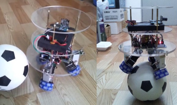
If you want a different kind of feedback systems challenge, ditch the Segway-style robots and build one that can balance on a ball. UFactory is a startup in Shenzhen, and this impressive little guy is a way of showing their skills applied to the classic inverted pendulum. At nearly 18 inches tall and weighing just over six pounds, the robot boasts a number of features beyond an accelerometer and gyroscope: it has both a WiFi module and a camera, and can be controlled via a homemade remote control or a Kinect.

The build uses plastic omni-directional wheels attached to 3 brushed dc motors, which attach to the base of the robot with custom-made aluminum brackets. The UFactory gang constructed the robot’s body out of three acrylic discs, which hold the electronics directly above the wheels. The brain seems to be an STM32 microcontroller that connects up to the motors and to the sensors.

You won’t find the code on their Instructable yet, but according to the comments they have plans to make the entire project open source. If you’re desperate for more details, the UFactory team seems willing to provide source code and other information via email. Make sure you see the video after the break, particularly the end where they demonstrate interference and carrying loads. This isn’t the first ball pendulum we’ve seen; take a trip down memory lane with the BallP ball balancing robot from 2010.

Continue reading “Building A Ball-Balancing Robot”

Linear Optical Encoder

dsc03989

Optical encoders are nothing new; they can be found in everything from mice to printers. They’re great for allowing DC motors to know their exact position and even current direction. If this is sounding like old hat, it’s because we’ve shown you rotational versions before.

[Chris] uses the same concept, but produced a linear optical encoder instead of rotational. His setup is much like whats used in non stepper-motor CNC and RepRap mills, allowing ordinary DC motors to know their position within a plane. It’s a quick tutorial, but we liked the detail and it reminded us we need to finish that DC motor based mill thats still a pile of parts in the closet. Check out a video of [Chris’] in action after the break. Continue reading “Linear Optical Encoder”

RCDC: DC Motor Control Via Servo Signals

[youtube=http://www.youtube.com/watch?v=x2Hn8No5oFQ]

[Spikenzie]  has put together this nice kit for controlling a DC motor with RC servo signals. He’s using a PIC12F629 to convert the signal to PWM. As you can see in the video above, it seems to work quite well. It is in a neat and tidy package and available as a kit. We have to admit though, what caught our eye was the prototype. Even though it is a kit for sale, it looks as though they plan on releasing the PCB files and code.

Persistence Of Vision Propeller Clock

[Jon Stanley] has a nice write up on a POV propellor clock powered by a PIC microcontroller. He improved on the original design by [Bob Blick]. Jon tried a few different methods of powering the spinning circuit, some of which could be handy for other projects. As a double plus good bonus, schematics and code are all linked on the site. This clock would look nice and sinister sitting on any mad scientist’s dresser.

RepRap Pinch Wheel Extruder

pinchwheel

What you see above is the culmination of [Zach Smith]’s work building a pinch wheel style extruder for the RepRap. The current RepRap 3D printer uses a screw mechanism to push 3mm polymer filament into a heating barrel where it is melted and then extruded through a fine nozzle. [Zach]’s new version uses a drive gear from SDP/SI mounted directly to the DC motor we saw him teardown earlier. He’s redesigned the carrier for the extruder as well. It’s now much lighter and has provisions for mounting current and future controller electronics along with a magnetic rotary encoder. In the last two days, he’s been doing real world testing. It’s been doing well, but he’s learning to do things like always using a full spool and not trying to run short lengths back to back.