The perfect antenna is the holy grail of amateur radio. But antenna tuning is a game of inches, and since the optimum length of an antenna depends on the frequency it’s used on, the mere act of spinning the dial means that every antenna design is a compromise. Or perhaps not, if you build this infinitely adjustable capstan-winch dipole antenna.
Dipoles are generally built to resonate around the center frequency of one band, and with allocations ranging almost from “DC to daylight”, hams often end up with a forest of dipoles. [AD0MZ]’s adjustable dipole solves that problem, making the antenna usable from the 80-meter band down to 10 meters. To accomplish this feat it uses something familiar to any sailor: a capstan winch.
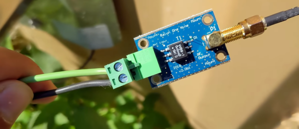
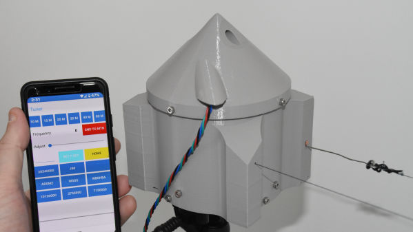
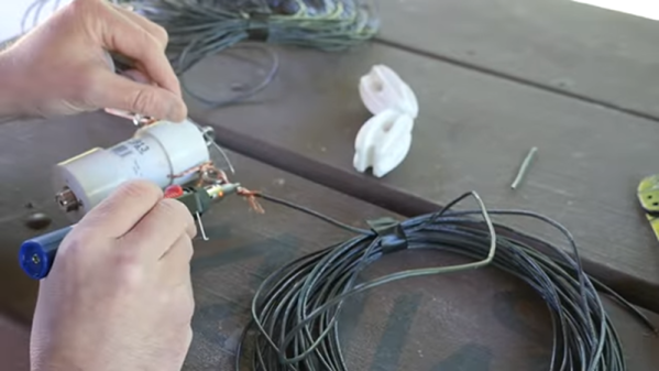
The feedpoint of the antenna contains a pair of 3D-printed drums, each wound with a loop of tinned 18-gauge antenna wire attached to some Dacron cord. These make up the adjustable-length elements of the antenna, which are strung through pulleys suspended in trees about 40 meters apart. Inside the feedpoint enclosure are brushes from an electric drill to connect the elements to a 1:1 balun and a stepper motor to run the winch. As the wire pays out of one spool, the Dacron cord is taken up by the other; the same thing happens on the other side of the antenna, resulting in a balanced configuration.
We think this is a really clever design that should make many a ham happy across the bands. We even see how this could be adapted to other antenna configurations, like the end-fed halfwave we recently featured in our “$50 Ham” series.