Laser cutters, waterjets, plasma cutters, CNC routers – most hackerspaces and even many dedicated home-gamers seem to have some kind of fancy tool for cutting sheet goods into intricate shapes. But with no access to a CNC machine and a need to cut a complex shape from sheet metal, [AlchemistDagger] cooked up this bare-bones and somewhat dangerous EDM rig to get the job done.
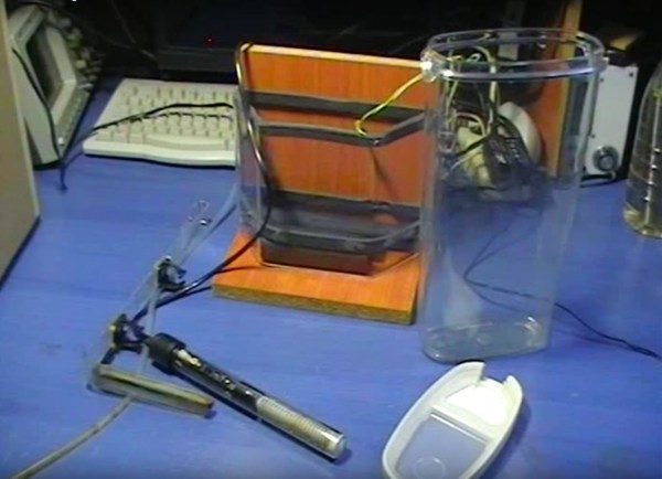
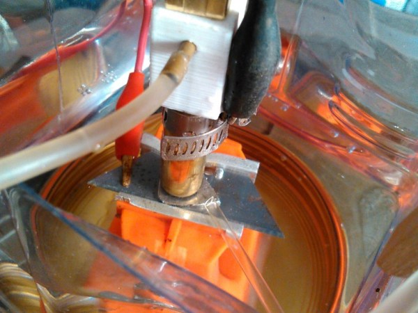
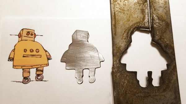
Electric discharge machining has been around for decades and is used a lot for harder metals like titanium and tool steel. The process makes sense to anyone who has seen contacts pitted and corroded by repeated arcing – an electric arc is used to remove metal from the workpiece, with a dielectric fluid used to cool the workpiece and flush away debris. For [AlchemistDagger]’s purposes, a lot of the complicated refinements, like high-frequency power supplies and precise tool positioning, were ignored. He built a simple linear slide to manually control the tool position, and the power supply was just a bridge rectifier connected to the 120-volt mains with some filter capacitors and a big light bulb as a ballast resistor. While the video below shows electrical conduit being notched, [AlchemistDagger] also made a brass cookie-cutter style tool to cut the Instructables logo from steel.
Obviously, mixing water and electricity is a recipe for disaster is you’re not careful, but this low-end EDM technique is a good one to file away for a rainy day. And if you’re looking for a little more sophistication in your homebrew EDM rig, we’ve got you covered there too. Continue reading “EDM For The Cheap And Adventurous”