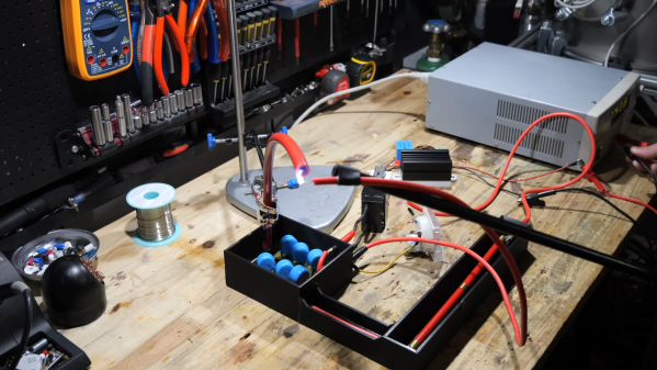
Got Junk? Then Build This Scrappy TEA Laser

A piece of glass, some bits of tinfoil, a sheet of plastic, a couple of razor blades, and a few assorted bits and bobs are all it takes to build this TEA nitrogen laser. Oh, and a 5,000-volt flyback supply with enough amperage to stop your heart. You’ll need that too.

Seriously, if you choose to follow [MultiverseCurator] ‘s example and build this laser, you’ll want to take the proper precautions. A transversely excited atmospheric laser is simple in concept, but there are plenty of ways for them to go wrong. Unlike the gas lasers used in laser cutters, there’s no enclosed resonator cavity or mirrors. Rather, the excitation takes place across a narrow gap between two electrodes, using atmospheric nitrogen as the lasing medium. This results in hard UV emissions, which means you can’t see them with the naked eye. Add to that the spark gap creating extremely loud discharges as the laser operates, and hazards abound. Proceed with caution.

Construction starts with a flat glass plate and a pair of large capacitors made from aluminum foil plates separated by a plastic dielectric. The razor blades are connected across the capacitors, separated by a narrow gap, with an inductor made from magnet wire in parallel. A spark gap made from nuts and bolts goes in series, and the whole assembly gets connected to a high-voltage power supply — [Multiverse] used a ZVS driver and a CRT flyback transformer with an eight-megohm resistor in series. The video below has all the build details.

It’ll take a little fiddling to get it lasing, and you’ll need something phosphorescent to see the UV light — a scrap of copy paper should do. But the results are pretty amazing for something made from scrap. If you want to take the design to the next level, you’ll want to check out [Les Wright]’s TEA laser build.

Continue reading “Got Junk? Then Build This Scrappy TEA Laser”

Flyback, Done Right

A common part used to create a high voltage is a CRT flyback transformer, having been a ubiquitous junk pile component. So many attempts to use them rely on brute force, with power transistors in simple feedback oscillators dropping high currents into hand-wound primaries, so it’s refreshing to see a much more nuanced approach from [Alex Lungu]. His flyback driver board drives the transformer as it’s meant to be used, in flyback mode relying on the sudden collapse of a magnetic field to generate an output voltage pulse rather than simply trying to create as much field as possible. It’s thus far more efficient than all those free running oscillators.

On the PCB is a UC3844 switch mode power supply controller driving the transformer at about 25 kHz through an IGBT. We’d be curious to know how closely the spec of the transformer is tied to the around 15 kHz it would have been run at in a typical TV, and thus what frequency would be the most efficient for it. The result as far as we can see it a stable and adjustable high voltage source with out all the high-current and over heating, something of which we approve.

Need to understand more about free running versus flyback? Read on.

Lessons Learned From A High-Voltage Power Supply

When you set out to build a 60,000-volt power supply and find out that it “only” delivers a measly 50,000 volts, you naturally have to dive in and see where things can be improved. And boy, did [Advanced Tinkering] find some things to improve.

First things first: if you haven’t seen [Advanced]’s first pass at a high-voltage supply, you should go check that out. We really liked the design of that one, and were particularly impressed with the attention to detail, all of which seemed to be wisely geared to the safe operation of the supply. But as it turns out, the margin of safety in the original design wasn’t as good as it could be. Of most concern was the need to physically touch the supply to control it, an obvious problem should something go wrong anywhere along the HV path, which includes a ZVS-driven flyback and an epoxy-potted Crockcroft-Walton voltage multiplier.

To make things a little more hands-off, [AT] added a pneumatically actuated switch to the supply, along with some indicator lights to help prevent him from leaving the supply powered up. He also reworked the low-voltage DC supply section, replacing a fixed-voltage supply and a DC-DC converter with a variable DC supply. This had the side benefit of providing a little bit more voltage to the ZVS driver, which goosed up the HV output a bit. The biggest change, though, was to the potted part of the HV section, which showed signs of arcing to the chassis. It turns out that even at 100% infill, 3D printed PLA isn’t a great choice for HV projects; more epoxy was the answer to that problem. Along with rewinding the primary on the flyback transformer, the power supply not only hit the 60-kV spec, but even went a little past that — and all without any of that pesky arcing.

We thought [Advanced Tinkering]’s first pass on this build was pretty slick, but we’re glad to see that it’s even better now. And we’re still keen to see how this supply will be put to use; honestly, the brief teaser at the end of the video wasn’t much help in guessing what it could be.

Continue reading “Lessons Learned From A High-Voltage Power Supply”

An Adjustable High-Voltage Power Supply Built With Safety In Mind

It’s not entirely clear why [Advanced Tinkering] needs a 50,000-volt power supply, but given the amount of work he put into this one, we’re going to guess it will be something interesting.

The stated specs for this power supply are pretty simple: a power supply that can be adjusted between 20kV and 50kV. The unstated spec is just as important: don’t kill yourself or anyone else in the process. To that end, [Advanced] put much effort into making things as safe as possible. The basic architecture of the supply is pretty straightforward, with a ZVS driver and an AC flyback transformer. Powered by a 24-volt DC supply and an adjustable DC-DC converter, that setup alone yields something around 20kV — not too shabby, but still far short of the spec. The final push to the final voltage is thanks to a three-stage Cockcroft-Walton multiplier made with satisfyingly chunky capacitors and diodes. To ensure everything stays safe in the high-voltage stage, he took the precaution of potting everything in epoxy. Good thing, too; tests before potting showed arcing in the CW multiplier despite large isolation slots in the PCB.

Aside from the potting, some really interesting details went into this build, especially on the high-voltage side. The 3D-printed and epoxy-filled HV connector is pretty cool, as is the special wire needed to keep arcs at bay. The whole build is nicely detailed, too, with care taken to bond each panel of the rack-mount case to a common ground point.

It’s a nice build, and we can’t wait to see what [Advanced Tinkering] does with it. In the meantime, if you want to get up to speed on handling high voltage safely, check out our HV primer.

Continue reading “An Adjustable High-Voltage Power Supply Built With Safety In Mind”

AC-DC Converter Is Reliable, Safe, And Efficient

When first starting an electronics project, it’s not uncommon to dive right in to getting the core parts of the project working. Breadboarding the project usually involves working with a benchtop power supply of some sort, but when it comes to finalizing the project the actual power supply is often glossed over. It’s not a glamorous part of a project or the part most of us want to be working with, but it’s critical to making sure projects don’t turn up with mysterious issues in the future. We can look to some others’ work to simplify this part of our projects, though, like this power supply from [hesam.moshiri].

The power supply is designed around a switch-mode topology known as a flyback converter. Flyback converters work by storing electrical energy in the magnetic field of a transformer when it is switched on, and then delivering that energy to the circuit when it is switched off. By manipulating the switching frequency and turns ratios of the transformer, the circuit can have an arbitrary output voltage. In this case, it is designed to take 220V AC and convert it to 8V DC. It uses a simplified controller chip to decrease complexity and parts count, maintains galvanic isolation for safety, and is built to be as stable as possible within its 24W power limitation to eliminate any potential issues downstream.

For anyone trying to track down electrical gremlins in a project, it’s not a bad idea to take a long look at the power supply first. Any noise or unwanted behavior here is likely to cause effects especially in projects involving sensors, ADC or DAC, or other low-voltage or sensitive components. The schematic and bill of materials are available for this one as well, so anyone’s next project could use this and even make slight adjustments to change the output voltage if needed. And, if this is your first introduction to switched-mode power supplies, check out this in-depth look at the similar buck converter circuit to better understand what’s going on behind the scenes on these devices.

Continue reading “AC-DC Converter Is Reliable, Safe, And Efficient”

2023 Hackaday Prize: The Primordial Soup’s On With This Modified Miller-Urey Experiment

It’s a pretty sure bet that anyone who survived high school biology has heard about the Miller-Urey experiment that supported the hypothesis that the chemistry of life could arise from Earth’s primordial atmosphere. It was literally “lightning in a bottle,” with a mix of gases like methane, ammonia, hydrogen, and water in a closed-loop glass apparatus and a pair of electrodes to provide a spark to simulate lightning lancing across the early prebiotic sky. [Miller] and [Urey] showed that amino acids, the building blocks of protein, could be cooked up under conditions that existed before life began.

Fast forward 70 years, and Miller-Urey is still relevant, perhaps more so as we’ve extended our reach into space and found places with conditions similar to those on early Earth. This modified version of Miller-Urey is a citizen science effort to update the classic experiment to keep up with those observations, plus perhaps just enjoy the fact that it’s possible to whip up the chemistry of life from practically nothing, right in your own garage. Continue reading “2023 Hackaday Prize: The Primordial Soup’s On With This Modified Miller-Urey Experiment”

Real Radar Scope CRT Shows Flights Using ADS-B

Real-time flight data used to be something that was only available to air traffic controllers, hunched over radar scopes in darkened rooms watching the comings and goings of flights as glowing phosphor traces on their screens. But that was then; now, flight tracking is as simple as pulling up a web page. But where’s the fun in that?

To bring some of that old-school feel to his flight tracking, [redacted] has been working on this ADS-B scope that uses a real radar CRT. As you can imagine, this project is pretty complex, starting with driving the 5FP7 CRT, a 5″ round-face tube with a long-persistence P7-type phosphor. The tube needs about 7 kV for the anode, which is delivered via a homebrew power supply complete with a custom flyback transformer. There’s also a lot going on with the X-Y deflection amps and beam intensity control.

The software side has a lot going on as well. ADS-B data comes from an SDR dongle using dump1090 running on a Raspberry Pi 3B. The latitude and longitude of each plane within range — about 5 nautical miles — is translated to vector coordinates, and as the “radar” sweeps past the location, a pip lights up on the scope. And no, you’re not seeing things if you see two colors in the video below; as [TubeTime] helpfully explains, P7 is a cascade phosphor that initially emits a bright-blue light with some UV in it, which then charges up a long-persistence green phosphor.

Even though multicolored icons and satellite imagery may be more useful for flight tracking, we really like the simple retro look [redacted] has managed to pull off here, not to mention the hackery needed to do it.

Continue reading “Real Radar Scope CRT Shows Flights Using ADS-B”