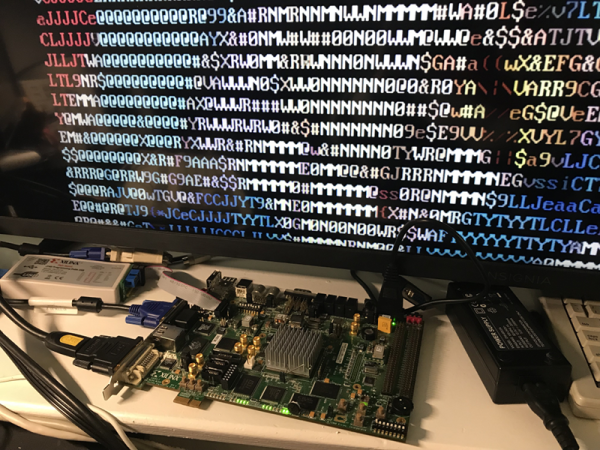
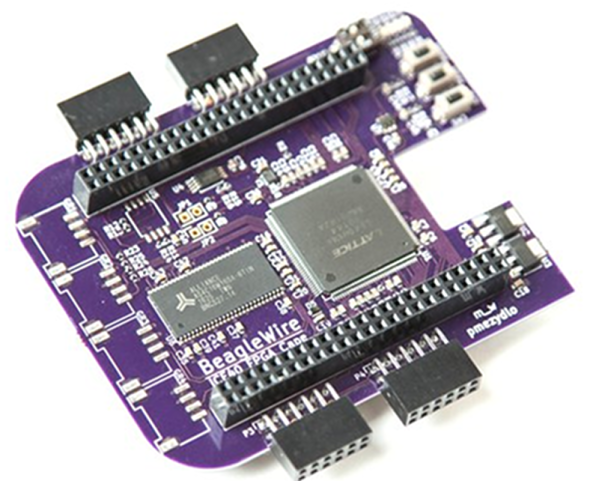
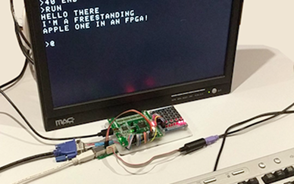
Hackaday Prize Entry: Programming FPGAs With Themselves

It’s been a few years since the introduction of the first Open Source toolchain for FPGAs. You would think a free and Open way to program FPGAs would be a boon for hardware development, but so far we’re really not seeing much in the way of a small, cheap, clever device that brings FPGAs to the masses.

We don’t know if [Luke]’s entry to the Hackaday Prize is the killer project that will do it, but it is very neat. He’s designed a tiny FPGA development board using a Lattice iCE40 FPGA that’s able to program itself over USB. It’s small, it’s cheap, it’s easy to use, and there are working examples of FPGA development using this board.

If you’re thinking this tiny little board looks familiar, you’re right. [Luke] has been working on a similar board, the A-Series, but this latest version has a USB port instead of pins for a JTAG adapter. This USB functionality is pretty clever — instead of using a seperate microcontroller, [Luke] is using the FPGA itself to reprogram the user configuration into a Flash chip. Once that’s up and running, the bootloader is removed and doesn’t consume any FPGA resources.

[Luke] is also working on an amazing hobbyist guide to FPGAs that leans heavily on the Open Source toolchain available for these Lattice FPGAs and his board. That’s a huge benefit to the community, and an excellent entry to the Hackaday Prize.

Homemade 6 GHz Radar, V3

The third version of [Henrik Forstén] 6 GHz frequency-modulated continuous wave (FMCW) radar is online and looks pretty awesome. A FMCW radar is a type of radar that works by transmitting a chirp which frequency changes linearly with time. Simple continuous wave (CW) radar devices without frequency modulation cannot determine target range because they lack the timing mark necessary for accurately time the transmit and receive cycle in order to convert this information to range. Having a transmission signal modulated in frequency allows for the radar to have both a very high accuracy of range and also to measure simultaneously the target range and its relative velocity.

Like the previous versions, [Henrik] designed a four-layer pcb board and used his own reflow oven to solder all the ~350 components. This process, by itself, is a huge accomplishment. The board, much bigger than the previous versions, now include digital signal processing via FPGA.

[Henrik’s] radar odyssey actually started back in 2014, where his first version of the radar was detailed and shared in his blog. A year later he managed to solve some of the issues he had, design a new board with significant improvements and published it again. As the very impressive version three is out, we wonder what version four will look like.

In the video of [Henrik] riding a bicycle in a circle in front of the radar, we can see the static light posts and trees while he, seen as a small blob, roams around:

Continue reading “Homemade 6 GHz Radar, V3”

Apple II FPGA

[Stephen Edwards] had some time one Christmas. So he took a DE2 FPGA board and using VHDL built a pretty faithful reproduction of an Apple II+ computer. He took advantage of VHDL modules for the 6502 CPU and PS/2 keyboard, and focused more on the video hardware and disk emulation.

According to [Stephen], you can think of the Apple II as a video display that happens to have a computer in it. The master clock is a multiple of the color burst frequency, and the timing was all geared around video generation. [Stephen’s] implementation mimics the timing, although using more modern FPGA-appropriate methods.

Continue reading “Apple II FPGA”

Learn FPGA Programming From The 1940s

We often think that not enough people are building things with FPGAs. We also love the retrotechtacular posts on old computer hardware. So it was hard to pass up [karlwoodward’s] post about the Chip Hack EDSAC Challenge — part of the 2017 Wuthering Bytes festival.

You might recognize EDSAC as what was arguably the first operational computer if you define a computer as what we think of today as a computer. [Maurice Wilkes] and his team invented a lot of things we take for granted today including subroutines (Wheeler jumps named after a graduate student).

The point to the EDSAC challenge was to expose people to creating designs with FPGAs, particularly using the Verilog hardware description language (HDL). If you want to follow along or run your own Chip Hack, the materials are available on the Web. You can see an FPGA driving a tape punch to create souvenir tapes in the video, below.

Some of the exercises are pretty simple and that’s perfect if you are starting out. The challenge uses a board with a Lattice ice40 FPGA and the open source toolchain for Lattice we’ve covered before. In fact, we’ve even done our own tutorials on the same basic device (but not the same board). Our final project generated PWM, not paper tape.

For the record, EDSAC was awesome. The execution unit was serial and processed bits that marched in one at a time over a mercury delay line. There is quite a bit of documentation and even some simulators, so if you ever wanted to get your hands into an old computer, this one isn’t a bad one to try.

Continue reading “Learn FPGA Programming From The 1940s”

The Linux FPGA

It was never unusual to have a CPU and an FPGA together. After all, each has different strengths and weaknesses. However, newer devices like the Xilinx Zynq have both a CPU and an FPGA in the same package. That means your design has to span hardware, FPGA configurations, and software. [Mitchell Orsucci] was using a Zynq device on a ArtyZ7-20 board and decided he wanted to use Linux to operate the ARM processor and provide user-space tools to interface with the FPGA and reconfigure it dynamically.

This sounds like a big project and it certainly isn’t trivial by any means. However, the Xilinx tools do a lot of the heavy lifting, including setting up the Linux kernel and a suitable root file system. The bulk of [Mitchell’s] work was in developing user space tools for Linux programs to interact with the FPGA hardware. You can see a short video demo below.

Continue reading “The Linux FPGA”

A Cold Hard Look At FPGAs

Researchers at the Delft University of Technology wanted to use FPGAs at cryogenic temperatures down around 4 degrees Kelvin. They knew from previous research that many FPGAs that use submicron fabrication technology actually work pretty well at those temperatures. It is the other components that misbehave — in particular, capacitors and voltage regulators. They worked out an interesting strategy to get around this problem.

The common solution is to move the power supply away from the FPGA and out of the cold environment. The problem is, that means long wires and fluctuating current demands will cause a variable voltage drop at the end of the long wire. The traditional answer to that problem is to have the remote regulator sense the voltage close to the load. This works because the current going through the sense wires is a small fraction of the load current and should be relatively constant. The Delft team took a different approach because they found sensing power supplies reacted too slowly: they created an FPGA design that draws nearly the same current no matter what it is doing.

Continue reading “A Cold Hard Look At FPGAs”

A Very 2017 Take On A BBC Micro

In the early 1980s, there were a plethora of 8-bit microcomputers on the market, and the chances are that if you were interested in such things you belonged to one of the different tribes of enthusiasts for a particular manufacturer’s product. If you are British though there is likely to be one machine that will provide a common frame of reference for owners of all machines of that era: The Acorn BBC Microcomputer which was ubiquitous in the nation’s schools. This 6502-driven machine is remembered today as the progenitor and host of the first ARM processors, but at the time was notable for the huge array of built-in interfaces it contained. Its relatively high price though meant that convincing your parents to buy you one instead of a ZX Spectrum was always going to be an uphill struggle.

So, you never owned a BBC Micro, and this has scarred you for life. Never mind, all is not lost, for now you can have that Acorn experience without scouring eBay for a classic micro, by running one entirely in silicon on a myStorm FPGA board.

To be fair, running classic hardware on an FPGA is nothing new and there have been a few BBC Micros implemented in this way, not to mention an Acorn Atom. But this project builds on the previous FPGA BBC Micros by porting it entirely to Verilog and incorporating some of the bug fixes from their various forks. There are screenshots of the result running several classic games, as well as test screens and a benchmark revealing it to be a faithful reproduction of a 2MHz BBC Micro.

We covered the myStorm board when it arrived last year. We’ve also brought you another FPGA board running as a coprocessor for a real BBC micro.

Thanks [monsonite] for the tip. He also alerts us that the myStorm board’s ARM microcontroller can now be programmed from the Arduino IDE.