VCF West: Adding A Front Panel To The 6502

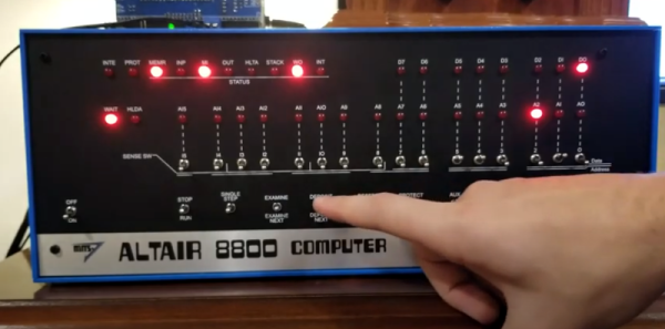
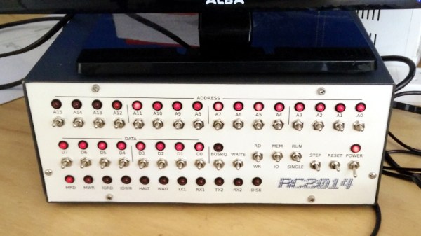
When you think about vintage computers from the 1970s, the first thing that should spring to mind are front panels loaded up with switches, LEDs, and if you’re really lucky, a lock with a key. Across all families of CPUs from the ’70s, you’ll find front panel setups for Z80s and 8080s, but strangely not the 6502. That’s not to say blinkenlights and panel switches for 6502-based computers didn’t exist, but they were astonishingly rare.

If something hasn’t been done, that means someone has to do it. [Alexander Pierson] built The Cactus, a  6502-based computer that can be controlled entirely through toggle switches and LEDs.

If you’re wondering why something like this hasn’t been built before, you only have to look at the circuitry of the 6502 CPU. The first versions of this chip were built with an NMOS process, and these first chips included bugs, undefined behavior, and could not be run with a stopped clock signal. These problems were fixed with the next chip spin using a CMOS process (which introduced new bugs), but the CMOS version of the 6502 would retain the contents of its registers with a stopped clock signal.

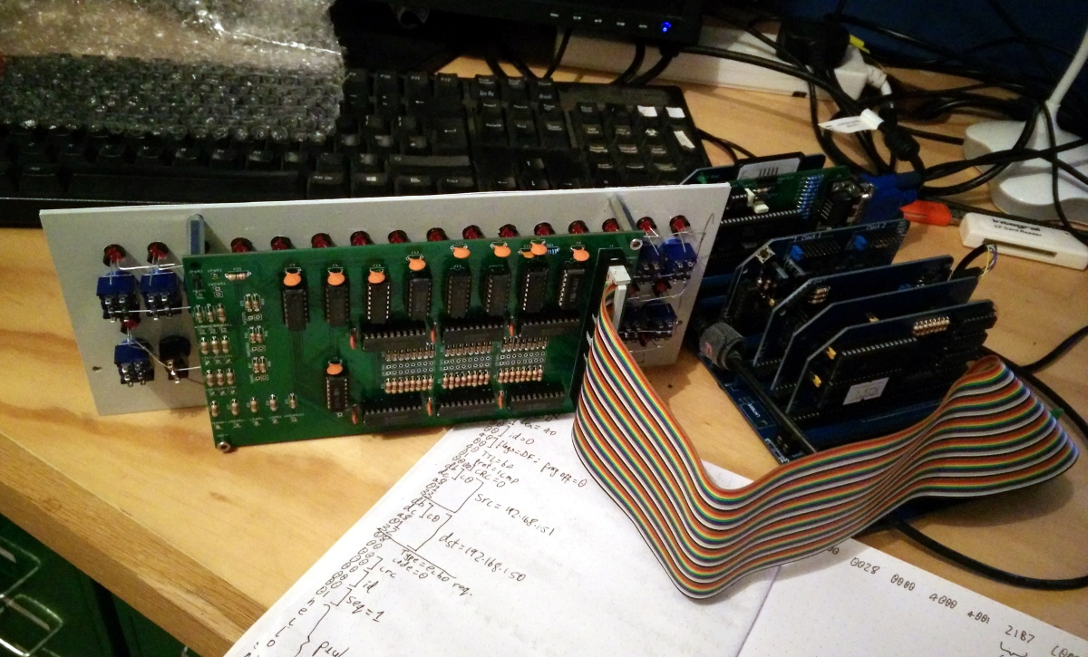
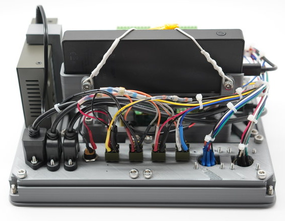
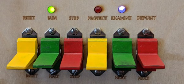
The specs for the Cactus computer are what you would expect from a homebrew 6502 system. The chip is a WDC 65C02S running at 1MHz, there’s 32k of RAM and a 16k EPROM, dual 6551s give serial access at various baud rates, and there are 16 bits of parallel I/O from a 65C22 VIA. The ROM is loaded up with OSI Basic. The real trick here is the front panel, though. Sixteen toggle switches allow the front panel operator to toggle through the entire address space, and eight flip switches can set any bit in the computer. Other controls include Run, Halt, Step, Examine, and Deposit, as you would expect with any front panel computer.

It’s a fantastic piece of work which I missed seeing at VCF East so I’m really glad [Alexander] made the trip between coasts. Cactus is truly something that hasn’t been done before. Not because it’s impossible, but simply because the state of the art technology from when the 6502 was new didn’t allow it. Now we have the chips, and the only limitation is finding someone willing to put in the work.

Cheap Front Panels With Dibond Aluminium

The production capability available to the individual hacker today is really quite incredible. Even a low-end laser engraver can etch your PCBs, and it doesn’t take a top of the line 3D printer to knock out a nice looking enclosure. With the wide availability of these (relatively) cheap machines, the home builder can churn out a very impressive one-off device on a fairly meager budget. Even low volume production isn’t entirely out of the question. But there’s still one element to a professional looking device that remains frustratingly difficult: a good looking front panel.

Now if your laser is strong enough to engrave (and ideally cut) aluminum sheets, then you’ve largely solved this problem. But for those of us who are plodding along with a cheap imported diode laser, getting text and images onto a piece of metal can be rather tricky. On Hackaday.io, [oaox] has demonstrated a cost effective way to create metal front panels for your devices using a print service that offers Dibond aluminum. Consisting of two thin layers of aluminum with a solid polyethylene core, this composite material was designed specifically for signage. Through various online services, you can have whatever you wish printed on a sheet of pre-cut Dibond without spending a lot of money.

As explained by [oaox], the first step is putting together the image you’ll send off to the printer using a software package like Inkscape. The key is to properly define the size of the Dibond plate in your software and work within those confines, otherwise the layout might not look how you expected once the finish piece gets back to you. It’s also important to avoid lossy compression formats like JPEG when sending the file out for production, as it can turn text into a mushy mess.

When you get the sheet back, all you need to do is put your holes in it. Thanks to the plastic core, Dibond is fairly easy to cut and drill as long as you take your time. [oaox] used a step drill for the holes, and a small coping saw for the larger openings. The final result looks great, and required very little effort in the grand scheme of things.

But how much does it cost? Looking around online, we were quoted prices as low as $7 USD to do a full-color 4×4 inch Dibond panel, and one site offered a 12×12 panel for $20. For a small production run, you could fit several copies of the graphics onto one larger panel and cut them out with a bandsaw; that could drop the per-unit price to only a couple bucks.

We’ve seen some clever attempts at professional looking front panels, from inkjet printing on transparencies to taking the nuclear option and laser cutting thin plywood. This is one of those issues the community has been struggling with for years, but at least it looks like we’re finally getting some decent options.

Radio Receiver Or Art? Why Not Both?

We’ve heard it said before that you should build things twice. Once to learn how to build it and the second time to build it right. [AA7EE] must agree. He was happy with his homebrew regenerative receiver that he called Sproutie. But he also wanted to build one more and use what he learned to make an even better receiver. The Sproutie Mark II was born.

This isn’t some rip off of an old P-Box kit either. [AA7EE] used a four-device RF stage with FET isolation back to the antenna and a regulated power supply. Plug in coils allow reception on multiple bands ranging from about 3 to 13 MHz. There’s an audio stage with multiple selectable audio filters, and–the best part–a National HRO tuning dial that is a work of art all by itself.

Continue reading “Radio Receiver Or Art? Why Not Both?”

Hackaday Links: June 22, 2014

hackaday-links-chain

Solar Freakin’ Roadways! There’s been a lot of talk about how solar freakin’ roadways are an ill-conceived idea, and now [Dave Jones] is weighing in on the subject. Highlights include a quarter of the solar power generated being used to light the LEDs that form the lane markers, something that could easily be accomplished with paint. Oh, the solar freakin’ roadway campaign is over. Just over $2.2 million, if you’re wondering.

The Game Boy Micro is the best way to play GBA games, but finding one for a reasonable price just isn’t going to happen. [John Sparks] is making his own Macro Micros by casemodding a DS Lite.On the subject of Game Boy mods, [koji-Kendo] is improving the common frontlight Game Boy Color mod with optically clear UV curing glue. Without glue on the left, with glue on the right.

Need to label a panel with the function of all your switches and dials? Yeah, you could drop the panel into an engraver, till the engraved letters with enamel, or do some electroetching. You can also buy a pack or rub-on letters, available in any Michaels, Hobby Lobby, or the like.

MSI Afterburner is a utility that allows you to play with settings and monitor performance on MSI graphics cards. [Stephen] made a little device for MSI Afterburner that displays the current FPS and GPU load on an external LCD. Handy, seeing as how FPS and GPU load is the one thing you’ll want to know when you’re gaming fullscreen.

Realtime cloudmaps of the Earth. Using reasonably recent images take from five geostationary satellites, you can stitch together a real-time cloud map of the entire Earth. Here’s the software to do it. Now all you need is a projector and pair of frosted acrylic hemispheres, and you have a real-time globe.

Say you have a Kickstarter in the works, and you’re trying to figure out all the ways to get some buzz from the Internet public.. Here’s how you get it to the front page of hackaday.io using a bit of Perl. “So far, this page has been updated 02578 times.”

OLED display, blue LED and Smartcard

Developed On Hackaday: Front Panels And Beta Testers Program

mooltipass front panel

We’re pretty sure that most of our readers already know it by now, but we’ll tell you anyway: the Hackaday community (writers and readers) is currently developing an offline password keeper, the Mooltipass. As it has been more than two weeks since we wrote an article about our progress, today’s will be about the Mooltipass front panels and our beta testers program.

At the end of our mechanical design rundown article we showed that we were originally planning to put a slightly tinted acrylic panel on top of our device. We however could still make out the Mooltipass’ insides, which wasn’t in line with the nice professional look we wanted. We then designed another front panel, one which was transparent above the OLED screen/LEDs and opaque (black) on top of the rest. To our surprise the result still wasn’t as good as we had hoped, as the contrast between the front panel and the screens/LEDs was too big. We finally came up with the panel shown above (see GitHub repository folder) which combines the two techniques previously described. As it is still in China, we’ll show you the final result when we get it in our hands.

We launched around 10 case prototypes in production, they will soon be shipped to our current contributors/advisers together with the smart cards chosen by Hackaday readers. In the meantime we sent our official call for beta testers to our mailing list recipients and hackaday.io followers, in which we asked them to fill a small form that will allow us to know them a bit better. We asked about their home/work computer setup, their level of expertise, their willingness to contribute to the prototype cost and finally specifics about who would use the Mooltipass they’d receive. We are targeting a broad range of users but also testers that will provide us with detailed feedback and clear bug reports.

We also spent quite a while searching for cheaper alternate parts that could be sourced in relatively big quantities. This is usually an overlooked aspect of a project so we preferred to tackle this as soon as possible. In a few weeks the contributors and I will receive all the components required to assemble our final prototype (front panels / case / top & bottom PCBs / smart cards) and it will be time to write a new update. Want to stay informed? You can join the official Mooltipass Google Group or follow us on Hackaday Projects.

OLED display, blue LED and Smartcard

Developed On Hackaday: The Top PCB Dilemna

The Hackaday community offline password keeper is slowly coming together. A few days ago we received the top PCB for Olivier’s design (shown above). If you look at the picture below, you may see the problem we discovered when opening our package: the soldermask was the wrong color! Given the board is meant to be placed behind a tinted acrylic panel, this was quite a problem…

After using some spray paint, we managed to get to the point shown in the bottom left of the picture. The next task was to find the best way to illuminate the input interface with reverse mount LEDs. Using a CNC mill we machined openings (top right PCB) but also removed some epoxy on both PCB’s sides, thinking it would provide a better light diffusion. We then wrote part of the Mooltipass PWM code and took these pictures:

Continue reading “Developed On Hackaday: The Top PCB Dilemna”

Designing A Front Panel For A DIY Project

DIY Front Panel


When building a one-off DIY project, appearances tend to be the least of our priorities. We just want to get the device working, and crammed into some project case. For those that like to build nicer looking prototypes [JumperOne] came up with a slick method of building a custom front panel for your DIY project.

The first step is to get the dimensions correct. You CAD tool will generate these from your design. [JumperOne] took these measurements into Inkscape, an open source vector graphics tool. Once it’s in Inkscape, the panel can be designed around the controls. This gets printed out and aligned on a plastic enclosure, which allows the holes to be marked and drilled.

With the electronics in place, the front panel gets printed again on a general purpose adhesive sheet. Next up is a piece of cold laminating film, which protects the label. Finally, holes are cut for the controls. Note that the display and LEDs are left covered, which allows the film to diffuse the light. The final result looks good, and can provide all the needed instructions directly on the panel.

[Thanks to Ryan for the tip]