Everyone who deals with electronics knows that grounding is important. Your house has a copper rod in the ground. But [Kristen K6WX] has news: the idea of ground is kind of a myth. She explained at a talk at the recent ARRL National Convention, and if you didn’t make it, you can watch it in the video below.
The problem is analogous to finding something that is standing still. You really can only talk about something standing still relative to something else. Sure, you might be standing still outside a building, but seen from the moon, you and the building are spinning around at about one revolution per day. If you were sitting on the sun and not burning up, you’d see lots of motion of everything, and, of course, the sun itself is moving in the right frame of reference.
Grounding problems and unwanted noise in electrical systems can often lead to insanity. It can seem like there’s no method to the madness when an electrical “gremlin” caused by one of these things pops its head out. When looking more closely, however, these issues have a way of becoming more obvious. In a recent video, [Fesz Electronics] shows us how to investigate some of these problems by looking at a small desktop power supply, modelling it in LTSpice, and reducing the noise on the power supply’s output.
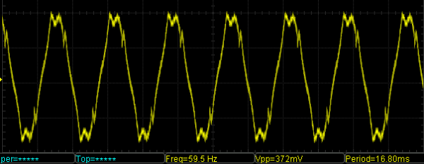
While everything in this setup is properly grounded, including the power supply and oscilloscope, the way the grounding systems interact can contribute to the high amount of noise. This was discovered by isolating the power supply from earth ground using electrical tape (not recommended as a long-term solution) and seeing that the noise was reduced. However, the ripple increased substantially, so a more permanent fix was needed. For that, the power supply was modelled in LTSpice. This is where a key discovery was made: since all the parts of the power supply aren’t ideal, noise can be introduced from the actual real-life electrical behavior of some of the parts. In this case, it was non-ideal capacitance in the transformer.
According to the model, this power supply could be improved by adding a larger capacitor across the output leads, and also by increasing their inductance. A large capacitor was soldered in the power supply and an iron ferrule was added, which decreased the noise level from 100 mV to around 20. Still not perfect, but a much needed improvement to the simple power supply. If, on the other hand, you want to make sure you eliminate that transformer’s capacitance completely, you can always go with a transformerless power supply. That carries other risks, though.
Invariably when we write about living on Mars, some ask why not go to the Moon instead? It’s much closer and has a generous selection of minerals. But its lack of an atmosphere adds to or exacerbates the problems we’d experience on Mars. Here, therefore, is a fun thought experiment about that age-old dream of living on the Moon.
Inhabiting Lava Tubes
The Moon has even less radiation protection than Mars, having practically no atmosphere. The lack of atmosphere also means that more micrometeorites make it to ground level. One way to handle these issues is to bury structures under meters of lunar regolith — loose soil. Another is to build the structures in lava tubes.
A lava tube is a tunnel created by lava. As the lava flows, the outer crust cools, forming a tube for more lava to flow through. After the lava has been exhausted, a tunnel is left behind. Visual evidence on the Moon can be a long bulge, sometimes punctuated by holes where the roof has collapsed, as is shown here of a lava tube northwest from Gruithuisen crater. If the tube is far enough underground, there may be no visible bulge, just a large circular hole in the ground. Some tubes are known to be more than 300 meters (980 feet) in diameter.
Lava tubes as much as 40 meters (130 feet) underground can also provide thermal stability with a temperature of around -20°C (-4°F). Having this stable, relatively warm temperature makes building structures and equipment easier. A single lunar day is on average 29.5 Earth days long, meaning that we’ll get around 2 weeks with sunlight followed by 2 weeks without. During those times the average temperatures on the surface at the equator range from 106°C (224°F) to -183°C (-298°F), which makes it difficult to find materials to withstand that range for those lengths of time.
In The Martian we saw what kind of hacking was needed to stay alive for a relatively short while on Mars, but what if you were trying to live there permanently? Mars’ hostile environment would affect your house, your transportation, even how you communicate. So here’s a fun thought experiment about how you’d live on Mars as part of a larger community.
Not Your Normal House
Radiation on Mars comes from solar particle events (SPE) and galactic cosmic radiation (GCR). Mars One, the organization planning one-way trips to Mars talks about covering their habitats in several meters of regolith, a fancy word for the miscellaneous rocky material covering the bedrock. Five meters provides the same protection as the Earth’s atmosphere — around 1,000 g/cm2 of shielding. A paper from the NASA Langley Research Center says that the largest reduction comes from the top 15 to 20 cm of regolith. And so our Mars house will have an underlying structure but the radiation protection will come from somewhere between 20 cm to a few meters of regolith. Effectively, people will be living underground.
On Earth, producing water and air for your house is not something you think of doing, let alone disposing of exhaled CO2. But Mars houses will need systems for this and more.
The electrical grid transmits power over wires to our houses, and our Bryan Cockfield has covered it very well in his Electrical Grid Demystified series, but what part does the earth ground play? It’s commonly known to be used for safety, but did you know that in some cases it’s also used for power transmission?
Typical House Grounding System
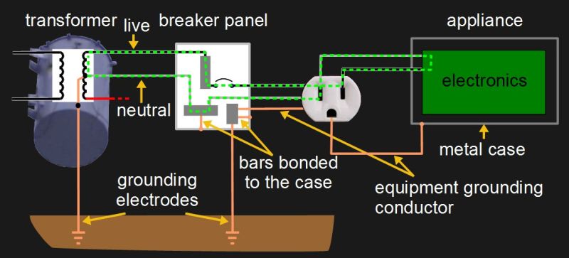
A pretty typical diagram for the grounding system for a house is shown here, along with a few of the current carrying conductors commonly called live and neutral. On the far left is the transformer outside the house and on the far right is an appliance that’s plugged in. In between them is a breaker panel and a wall socket of the style found in North America. The green dashed line shows the normal path for current to flow.
Notice the grounding electrodes for making an electrical connection with the earth ground. To use the US National Electrical Code (NEC) as an example, article 250.52 lists eight types of grounding electrodes. One very good type is an electrode encased in concrete since concrete continues to draw moisture from the ground and makes good physical contact due to its weight. Another is a grounding rod or pipe at least eight feet long and inserted deep enough into the ground. By deep enough, we mean to include factors such as the fact that the frost line doesn’t count as a good ground since it has a high resistance. You have to be careful of using metal water pipes that seemingly go into the ground, as sections of these are often replaced with non-metallic pipes during regular maintenance.
Notice also in the diagram that there are places where the various metal cases are connected to the grounding system. This is called bonding.
Now, how does all this system grounding help us? Let’s start with handling a fault.
These magical creatures crop up out of nowhere and fry your electronics or annoy your ear holes. Understanding them will doubtless save you money and hassle. The ground loop in a nutshell is what happens when two separate devices (A and B) are connected to ground separately, and then also connected to each other through some kind of communication cable with a ground, creating a loop. This provides two separate paths to ground (B can go through its own connection to ground or it can go through the ground of the cable to A and then to A’s ground), and means that current may start flowing in unanticipated ways. This is particularly noticeable in analog AV setups, where the result is audio hum or visible bars in a picture, but is also sometimes the cause of unexplained equipment failures. Continue reading “WTF Are Ground Loops?”→
[Bertho] sent in a great tutorial on terminating transmission lines. If you’ve ever tried to send a high frequency signal a long way down a wire, you know the problems that can crop up due to electronic strangeness. Luckily [Bertho]’s tutorial explains just about everything, from where and when to terminate a cable and why signals get screwed up in long wires.
[Bertho] begins his lesson by taking two oscilloscopes and 20 m of CAT5 cable with the twisted pairs wired in series to make an 80 meter long transmission line. A ~100kHz square wave was sent down the cable after being displayed on the first oscilloscope, and picked up on the other end by the second oscilloscope. It’s a great way to show the changes in a signal over a long cable run, and how small changes in the circuit (just adding a simple resistor) can affect the signal coming out of a cable.
It’s a great post that demystifies the strange electrical gremlins that pop up when you’re running a length of wire. Great job, [Bertho].