High Speed Imaging Of Magnetic Fields

Some time before experimenting with MRI machines and building his own CT scanner, [Peter Jansen] wanted to visualize magnetic fields. One of his small side projects is building tricoders — pocket sensor suites that image everything — and after playing around with the magnetometer function on his Roddenberry-endorsed tool, he decided he had to have a way to visualize magnetic fields. After some work, he has the tools to do it at thousands of frames per second. It’s a video camera for magnetic fields, pushing the boundaries of both magnetic imaging technology and the definition of the word ‘camera’.

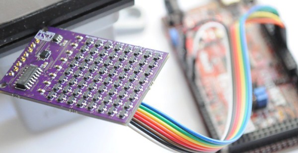
When we last looked at [Peter]’s Hall effect camera, the device worked, but it wasn’t necessarily complete. The original design used I2C I/O multiplexers for addressing each individual ‘pixel’ of the Hall effect array, limiting the ‘framerate’ of the ‘camera’ to somewhere around 30 Hz. While this would work for visualizing static magnetic fields, the more interesting magnetic fields around us are oscillating — think motors and transformers and such. A much faster magnetic camera was needed, and that’s what [Peter] set out to build.

Instead of an I/O expander, [Peter] re-engineered his design to use analog multiplexers and a binary counter to cycle through each pixel, one at a time. Basically, the new circuit uses two analog muxes for the columns and rows of the Hall effect array, a binary counter to cycle through each pixel at Megahertz speed, and a fast ADC to read each value. It is, bizarrely, the 1970s way of doing things; these are simple chips, and the controller (a Chipkit Max32) only needs to read a single analog value and clock the binary counter really fast.

With the new design, [Peter] is able to get extremely fast frame rates of about 2,000 Hz. That’s fast enough for some beautiful visualizations of spinning motors and transformers, seen in the video below. Further improvements may include three-axis magnetometers, which should allow for some spectacular visualizations similar to [Ted Yapo]’s 3D magnetic field scanner.

Continue reading “High Speed Imaging Of Magnetic Fields”

Imaging Magnetism With A Hall Effect Camera

[Peter Jansen] is the creator of the Open Source Tricorder. He built a very small device meant to measure everything, much like the palm-sized science gadget in Star Trek. [Peter] has built an MRI machine that fits on a desktop, and a CT scanner made out of laser-cut plywood. Needless to say, [Peter] is all about sensing and imaging.

[Peter] is currently working on a new version of his pocket-sized science tricorder, and he figured visualizing magnetic fields would be cool. This led to what can only be described as a camera for magnetism instead of light. It’s a device that senses magnetic fields in two directions to produce an image. It’s cool, and oddly, electronically simple at the same time.

Visualizing magnetic fields sounds weird, but it’s actually something we’ve seen before. Last year, [Ted Yapo] built a magnetic imager from a single magnetometer placed on the head of a 3D printer. The idea of this device was to map magnetic field strength and direction by scanning over the build platform of the printer in three dimensions. Yes, it will create an image of field lines coming out of a magnet, but it’s a very slow process.

Instead of using just one magnetic sensor, [Peter] is building a two-dimensional array of magnetic sensors. Basically, it’s just a 12×12 grid of Hall effect sensors wired up to a bunch of analog multiplexers. It’s a complicated bit of routing, but building the device really isn’t hard; all the parts are easily hand-solderable.

While this isn’t technically a camera as [Peter] would need box or lens for that, it is a fantastic way to visualize magnetic fields. [Peter] can visualize magnets on his laptop screen, with red representing a North pole and green representing the South pole. Apparently, transformers and motors look really, really cool, and this is a perfect proof of concept for the next revision of [Peter]’s tricorder. You can check out a video of this ‘camera’ in action below.

Continue reading “Imaging Magnetism With A Hall Effect Camera”

Interactive Board Prompts Moves For Checkers And Chess

In terms of equipment, chess and checkers are simple games — just a handful of pieces and a checkered gameboard. The simplicity belies the underlying complexity of the games, though, and goes a long way toward explaining their popularity over the millennia.

Increasing the complexity with an interactive game board for chess and checkers might seem counterintuitive, then. But [Bogdan Berg]’s project aims to not only teach checkers and chess but to make games a little more exciting and engaging. Looking a little like a tabletop version of the interactive dance floors we’ve been seeing a lot of lately, the board is built from laser-cut acrylic with plywood dividers to isolate all 64 squares. Neopixels and Hall-effect sensors are mounted to custom PCBs that stretch the length of a row and are wired to an Arduino Mega with lots of IO. Game pieces are colorful fridge magnets. [Bogdan]’s current program supports checkers and keeps track of where the pieces have been moved relative to their starting position and prompts users with possible legal moves.

[Bogdan]’s board already looks like a lot of fun in the video below, and we like the quality of the build and the unobtrusive nature of the interactivity. When he gets around to implementing chess, though, he might want something fancier than fridge magnets for game pieces.

Continue reading “Interactive Board Prompts Moves For Checkers And Chess”

Tracking The Hamster Marathon

[Michelle Leonhart] has two Roborovski hamsters (which, despite the name, are organic animals and not mechanical). She discovered that they seem to run on the hamster wheel all the time. A little Wikipedia research turned up an interesting factoid: This particular breed of hamster is among the most active and runs the equivalent of four human marathons a night. Of course, we always believe everything we read on Wikipedia, but not [Michelle]. She set out to determine if this was an accurate statement.

She had already added a ball bearing to the critters’ wheel to silence it by cannibalizing an old VCR. What she needed was the equivalent of a hamster pedometer. A Raspberry Pi and a Hall effect sensor did the trick. At least for the raw measurement. But it still left the question: how much distance is a hamster marathon?

01_hamster_stride_measurement[Michelle] went all scientific method on the question. She determined that an average human female’s stride is 2.2 feet which works out to 2400 strides per mile. A marathon is 26.2 miles (based on the distance Pheidippides supposedly ran to inform Athens of victory after the battle of Marathon). This still left the question of the length of a hamster’s stride. Surprisingly, there was no definitive answer, and [Michelle] proposed letting them run through ink and then tracking their footsteps. Luckily, [Zed Shaw] heard about her plan on Twitter and suggested pointing a webcam up through the plastic bottom of the cage along with a scale. That did the trick and [Michelle] measured her hamster’s stride at about 0.166 feet (see right).

Now it was a simple matter of math to determine that a hamster marathon is just under 10,500 steps. Logging the data to SQLite via ThingSpeak for a month led [Michelle] to the conclusion: her hamsters didn’t run 4 marathon’s worth of steps in a night. In fact, they never really got much over 2 marathons.

Does [Michelle] have lazy hamsters, or did she just add to our body of scientific knowledge about rodents? We don’t know. But we couldn’t help but admire her methods and her open source data logging code would probably be useful for some non-hamster activities.

If you are super competitive, you could use [Michelle’s] data to handicap yourself and challenge your pets to a race. But it would probably be cooler to build them their own Starship Trooper-style walkers. Either way, you can check out [Michelle’s] little marathon runners in the video below.

https://vine.co/v/enpFetTQD75

gears

Raspberry Pi Opens Doors

The Raspberry Pi is a cheap credit card sized computer that has opened the doors of embedded Linux to millions of people. But in this case, it’s literally opening a door. The Computer Club at Western Michigan University had to move to a different room which brought with it a new challenge. The door handle was more difficult to turn than the old one. Nothing that a NEMA 17 stepper couldn’t handle, however.

After printing a few gears and wiring up an Easy Driver board between the Raspi and stepper motor, they had the basics of a door opener in place. A 5v relay is used to keep the power off the stepper when not in use, and a limit switch is used to monitor the position of the door handle while a Hall Effect sensor tells when the door is open and shut.

Be sure to check out the project as all source, parts list and schematics are available in case you have a simliar door that needs amending.

Firing Blanks With Laser Tag

glockLast year, [Tony] was asked to develop a lasertag system with ultimate realism. This meant a system that used a blank firing replica gun, and a system to detect blank rounds being fired. Very cool, and the way he went about it includes some interesting electronics.

Because the system requires a blank to be fired before shooting a laser at a target, the entire system must be able to detect a blank being fired. [Tony]’s first attempt used a piezo sensor to detect the shock from being fired. This system had a lot of noise and was ditched for a much better solution: a magnet mounted to the slide, and a hall effect sensor mounted to a 3D printed frame that turns this replica into a carbine.

A little bit of tweaking in software was required to inhibit the laser when the operator cocks the gun, but it looks – and sounds – really good. It’s also very, very realistic: the only way to shoot an opponent is to physically reload. Video below.

Continue reading “Firing Blanks With Laser Tag”

Adding An RPM Readout For A Home Made CNC Mill

rpm_lcd

[Rui] recently put the finishing touches on his homemade CNC mill, which utilizes a dremel-like rotary tool. The problem with using rotary tools for this kind of application is you don’t really have an accurate speed readout… so he designed his own RPM gauge.

The sensor is in itself very simple. He’s using a TLE4935L hall effect sensor, a spare 16FE88 microcontroller, a Nokia LCD, and one tiny neodymium magnet. The magnet has been carefully epoxied onto the motor fan, with the hall effect sensor close by. He’s also built a guard around it, just in case the magnet decides to fly off at high speeds.

During testing he hooked up the hall effect sensor to both his home-made circuit, and an oscilloscope to confirm his findings. Once he was assured everything was working properly he sealed it off and mounted the LCD above the spindle as a nice digital readout.

Continue reading “Adding An RPM Readout For A Home Made CNC Mill”