Measuring a magnetic field can be very easy with some pretty low tech, or it can be very high tech. It just depends on what kind of measurement you need and how much effort you want to expend. The very simplest magnetic sensors are reed switches. These are basically relays with no coil. Instead of a coil, an external magnet gets close enough to make or break the contacts in the reed. You see these a lot in, for example, door alarm sensors.
Then again, there’s no real finesse to a reed. It changes state when it sees enough of a magnetic field and that’s about all. You could use a compass with some sort of detection on the needle to get some more information about the field, but not much more. That was, however, how early magnetometers worked. Today, you have lots of options, including the nearly ubiquitous Hall effect sensor.
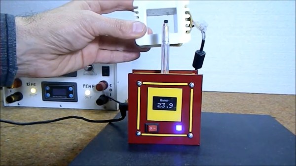
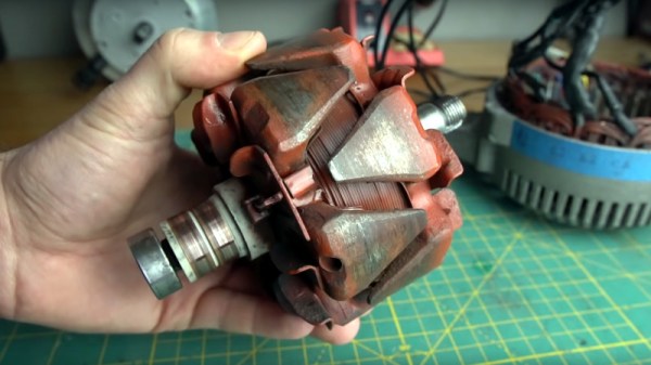
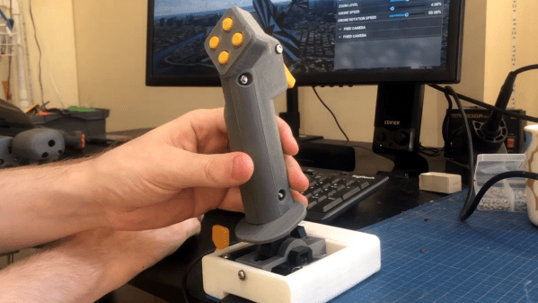
You might use a Hall effect to measure the magnetic button on a keyboard key coming down when you press it or the open and closed state of a valve. A lot of Hall effects see service as current monitors. Since a coil generates a magnetic field proportional to the current through it, a magnetic sensor can estimate the current in a coil of wire without any physical contact. Hall effects can also watch a magnet go by in a linear motion system or a rotating system to get an idea of position or speed. For example, check out this brushless motor controller that uses three sensors to understand the motor’s position.
History
 Edwin Hall identified the effect in 1879. The basic idea is simple: an electrical conductor carrying current will exhibit changes due to an external magnetic field nearby. These changes show up as voltage you measure across the conductor. Normally, the voltage across a conductor will be nearly zero, but with a magnetic field, you’ll get a non-zero reading in proportion to the magnetic field strength in a particular plane, as we’ll see shortly.
Hall effect sensors are just one type of modern magnetometer. There are many different kinds including those that use inductive pickup coils that may or may not rotate or a fluxgate, which is a special type of coil. Some use a scale or a spring to measure force against another magnet — sometimes microscopically. You can even detect a magnetic field using optical properties like the Kerr effect or Faraday rotation.