In terms of equipment, chess and checkers are simple games — just a handful of pieces and a checkered gameboard. The simplicity belies the underlying complexity of the games, though, and goes a long way toward explaining their popularity over the millennia.
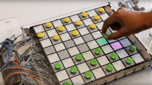
Increasing the complexity with an interactive game board for chess and checkers might seem counterintuitive, then. But [Bogdan Berg]’s project aims to not only teach checkers and chess but to make games a little more exciting and engaging. Looking a little like a tabletop version of the interactive dance floors we’ve been seeing a lot of lately, the board is built from laser-cut acrylic with plywood dividers to isolate all 64 squares. Neopixels and Hall-effect sensors are mounted to custom PCBs that stretch the length of a row and are wired to an Arduino Mega with lots of IO. Game pieces are colorful fridge magnets. [Bogdan]’s current program supports checkers and keeps track of where the pieces have been moved relative to their starting position and prompts users with possible legal moves.
[Bogdan]’s board already looks like a lot of fun in the video below, and we like the quality of the build and the unobtrusive nature of the interactivity. When he gets around to implementing chess, though, he might want something fancier than fridge magnets for game pieces.
Continue reading “Interactive Board Prompts Moves For Checkers And Chess”

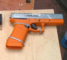 Last year, [Tony] was asked to develop a lasertag system with ultimate realism. This meant a system that used a blank firing replica gun, and a system to detect blank rounds being fired. Very cool,
 [Jack], a mechanical engineer, loom builder, and avid sailor wanted an autopilot system for his 1983 Robert Perry Nordic 40 sailboat with more modern capabilities than the one it came with. He knew a PC-based solution would work, but it was a bit out of reach. Once his son showed him an Arduino, though, he was on his way. He sallied forth and built