Why The Saturn V Used Kerosene For Its Hydraulics Fluid

We usually think of a hydraulic system as fully self-contained, with a hydraulic pump, tubing, and actuators filled with a working fluid. This of course adds a lot of weight and complexity that can be undesirable in certain projects, with the Saturn V Moon rocket demonstrating a solution to this which is still being used to this day. In a blast-from-the-past, a December 1963 article originally published in Hydraulics & Pneumatics details the kerosene-based hydraulics (fueldraulics) system for the S-1C stage’s gimbal system that controlled the four outer engines.

Rather than a high-pressure, MIL-H-5606 hydraulic oil-based closed loop as in the Saturn I, this takes kerosene from the high-pressure side of the F1 rocket engine’s turbopump and uses it in a single-pass system. This cuts out a separate hydraulic pump, a hydraulic reservoir, which was mostly beneficial in terms of reducing points of failure (and leaks), ergo increasing reliability. Such was the theory at the time at least, and due to issues with RP-1 kerosene’s relatively low flash point and differences in lubricity properties, ultimately RJ-1, RP-1 and MIL-H-5606 were used during checkout leading up to the launch.

In hindsight we know that this fueldraulic system worked as intended with all Saturn V launches, and today it’s still used across a range of aircraft in mostly jet engines and actuators elsewhere of the Boeing 777 as well as the F-35. In the case of the latter it only made the news when there was an issue that grounded these jets due to badly crimped lines. Since fueldraulics tends to be lower pressure, this might be considered a benefit in such cases too, as anyone who has ever experienced a hydraulic line failure can attest to.


Featured image: Gimbal systems proposed for the F-1, oxygen-kerosene engine with a fueldraulic system. (Source: Hydraulics & Pneumatics, 1963)

Building A Hydraulic System With 3D Printed SLA Resin Parts

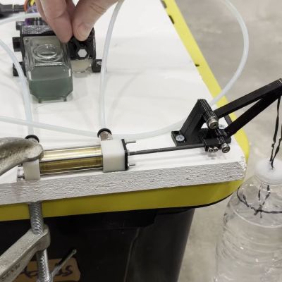
Showing off the 3D-printed hydraulics system. (Credit: Indeterminate Design, YouTube)

Hydraulics are incredibly versatile, but due to the pressures at which they operate, they are also rather expensive and not very DIY-friendly. This isn’t to say that you cannot take a fair shot at a halfway usable 3D-printed set of hydraulics, as [Indeterminate Design] demonstrates in a recent video. Although not 100% 3D-printed, it does give a good idea of how far you can push plastic-based additive manufacturing in this field.

Most interesting is the integration of the gear pump, 4-way selector valve, and relief valve into a single structure, which was printed with a resin printer (via the JLC3DP 3D print service). After bolting on the (also 3D printed) clear reservoir and assembling the rest of the structure including the MR63 ball bearings, relief spring valve, and pneumatic fittings it was ready to be tested. The (unloaded) gear pump could pump about 0.32 L/minute, demonstrating its basic functionality.

For the hydraulic cylinder, mostly non-3D printed parts were used, with a brass cylinder forming the main body. During these initial tests, plain water was used, followed by CHF11 hydraulic oil, with a pressure of about 1.3 bar (19 PSI) calculated afterward. This fairly low pressure is suspected to be caused by leaky seals (including the busted shaft seal), but as a basic proof of concept, it provides an interesting foundation for improvements.

Want a primer on hydraulics? We got you. MIT likes 3D printing with hydraulics, too (dead link, but the underlying paper link is still good).

Continue reading “Building A Hydraulic System With 3D Printed SLA Resin Parts”

Building A Hydraulic Loader For A Lawn Tractor

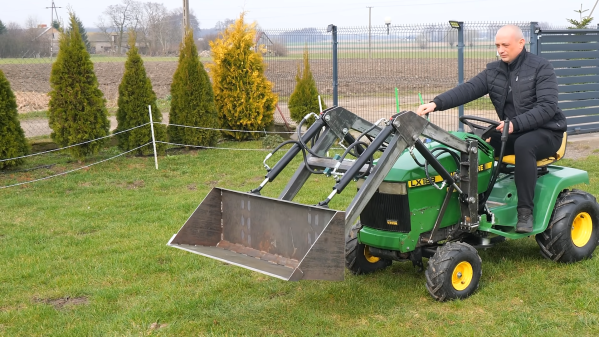
Lawn tractors are a great way to mow a large yard or small paddock. They save you the effort of pushing a mower around and they’re fun to drive, to boot. However, they can be even more fun with the addition of some extra hardware. The hydraulic loader build from [Workshop from Scratch] demonstrates exactly how.

The build is based around a John Deere LX188 lawn tractor, which runs a 17 horsepower Kawasaki engine and features a hydrostatic transmission. It’s a perfectly fine way to mow a lawn. In this case, though, it’s given new abilities with the addition of a real working loader. It’s fabricated from raw steel from the arms right down to the bucket. It’s all run from a hydraulic pump, which is mounted to the engine via an electromagnetic clutch. The clutch can be engaged when it’s desired to use the hydraulics to actuate the loader.

As you might expect, the humble lawn tractor isn’t built for this kind of work. Thus, to support the extra equipment, the mower was also given some frame reinforcements and a wider track for stability.

If you’re trying to give your neighbours mower envy, this is how you do it. Or, you could go another route entirely. Video after the break.
Continue reading “Building A Hydraulic Loader For A Lawn Tractor”

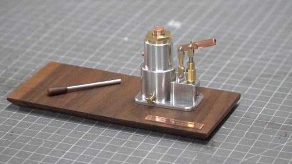
A 1/5th scale hydraulic jack model

Miniature Hydraulic Jack Is A Scale Marvel

Most hydraulic jacks are big tools that can lift upwards of 1000 kg but [Maker B]’s is quite a bit smaller than average.

The world’s smallest hydraulic jack is a tiny hand-machined model made out of tiny pieces of iron, brass and copper. But here’s the kicker: It’s a real hydraulic jack with real hydraulic fluid! At 1/5th scale, it obviously isn’t as strong as a full-size jack, but it can still easily lift an impressive 24 soda cans! Switching between the lathe and mill, [Maker B] shows how all the parts of the jack are made from stock metal in detail, and even explains in simple terms how a hydraulic jack works in this masterpiece of a video.

Over the years, we’ve seen plenty of tiny objects cranked out from stock pieces of metal — often bolts. But the fact that the end result here is a working tool, puts it into a decidedly less common niche. Of course, given what we’ve seen from [Maker B] in the past, it’s hardly a surprise.
Continue reading “Miniature Hydraulic Jack Is A Scale Marvel”

Building A Hydraulic Lego Excavator Using Standard Pneumatic Cylinders

Everyone already knows that Lego Technic is pretty rad when it comes to existing, pre-made kits, but there’s also quite a bit of hacking potential left. One such area is the lack of hydraulics in Lego Technic, an egregious oversight that [Brick Technology] simply had to correct. His effort results in a partially hydraulic, fully remote-controlled excavator. Rather than a traditional gear hydraulic pump as you’d expect in a real-life excavator, a custom peristaltic pump is used to move the fluid to the hydraulic cylinders (rams for our British and Oceanic friends).

The undercarriage is (sadly) purely electrical, with a slip-ring providing power to the electric final drives in the tracks, enabling it to spin around endlessly without limitations. Where the hydraulics come into play is in the excavator’s arm, with two hydraulic lift cylinders on the boom, one cylinder to control the stick, and a final cylinder to control the bucket. Rather than a hydraulic switch, the setup is simplified by using a single peristaltic pump per cylinder circuit.

Remote control and power are provided using the rather chonky BuWizz 3.0 Pro, which offers a wireless control link (here controlled using BrickController 2 on Android). Although original Lego cylinders were used, these are only intended for pneumatics, where it’s hoped that the used mixture of water and windscreen wiper fluid will prevent corrosion.

(Thanks to [Keith Olson] for the tip)

Continue reading “Building A Hydraulic Lego Excavator Using Standard Pneumatic Cylinders”

Robot Hand Looks And Acts Like The Real Thing

Throughout history, visions of the future included human-looking robots. These days we have plenty of robots, but they don’t look like people. They look like disembodied arms, cars, and over-sized hockey pucks concealing a vacuum cleaner. Of course there’s still demand for humanoid robots like Commander Data, but there are many challenges: eyes, legs, skin, and hands. A company known as Clone may have the solution for that last item. The Clone Hand is “the most human-level musculoskeletal hand in the world,” according to the company’s website.

The 0.75 kg hand and forearm offer 24 degrees of freedom and two hours of battery life. It sports 37 muscles and carbon fiber bones. The muscle fibers can cycle over 650,000 times. You can watch the hand in action in the video below.

There is a hydraulic pump that the company likens in size to a human heart. The hand can also sense for feedback purposes. If you want to build your own, you’ll have to figure it out yourself. The Clone Hand is proprietary, but it does show what is in the art of the possible. The company claims they cost under $3,000, but it isn’t clear if that’s their cost or a projected future retail price.

Of course, human hands aren’t always the perfect robot manipulator. But when you need a realistic hand, you really need it. We see a lot of attempts at realistic hands, and we have to say they are getting better.

Continue reading “Robot Hand Looks And Acts Like The Real Thing”

Impressive Sawdust Briquette Machine

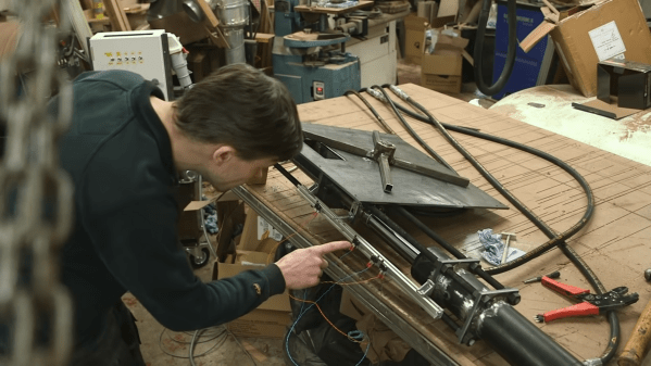
When you are a life long carpenter with an amazing workshop, you’re going to make a lot of saw dust, and managing its collection and storage poses quite a challenge. [Russ] from [New Yorkshire Workshop] built an impressive Briquette press to handle the problem.

It’s a hydraulic press that ingests  saw dust and spits out compressed briquettes ready for fueling his rocket mass heater. The build starts with a batch of custom, laser cut steel parts received from Fractory. The heart of the machine is a 300 mm stroke hydraulic cylinder with a beefy 40 mm rod. The cylinder had to be taken apart so that the laser cut mounting flanges could be welded, slowly so as not to deform the cylinder. The intake feed tube was cut from a piece of 40 mm bore seamless tube. A window was cut in the feed tube and funnel parts were welded to this cutout. The feed tube assembly is then finished off with a pair of mounting flanges. The feed tube assembly is in turn welded to the main feed plate which will form the base of the saw dust container. The hydraulic cylinder assembly is mated to the feed tube assembly using a set of massive M10 high tensile class 10.9 threaded rods. The push rod is a length of 40 mm diameter mild steel bar stock, coupled to the hydraulic cylinder using a fabricated coupling clamp. On the coupling clamp, he welded another bracket on which a bolt can be screwed on. This bolt helps activate the limit switches that control the movement of the hydraulic cylinder and the feed motor. Continue reading “Impressive Sawdust Briquette Machine”