Putting A Poor Man’s Vector Analyzer Through Its Paces

If anything about electronics approaches the level of black magic, it’s antenna theory. Entire books dedicated to the subject often merely scratch the surface, and unless you’re a pro with all the expensive test gear needed to visualize what’s happening, the chances are pretty good that your antenna game is more practical than theoretical. Not that there’s anything wrong with that — hams and other RF enthusiasts have been getting by with antennas that work without really understanding why for generations.

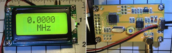
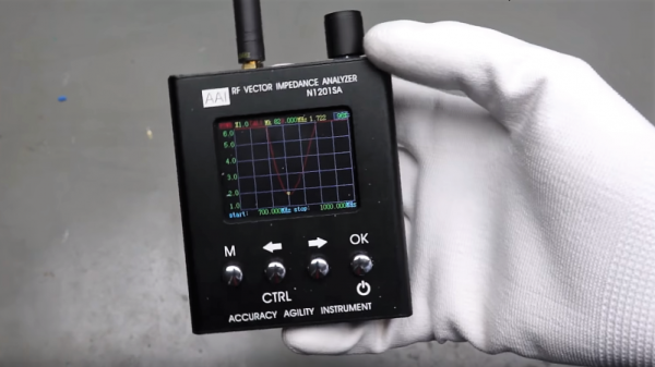
But we’re living in the future, and the tools to properly analyze antenna designs are actually now within the means of almost everyone. [Andreas Spiess] recently reviewed one such instrument, the N1201SA vector impedance analyzer, available from the usual overseas sources for less than $150. [Andreas]’s review does not seem to be sponsored, so it seems like we’re getting his unvarnished opinion; spoiler alert, he loves it. And with good reason; while not a full vector network analyzer (VNA) that will blow a multi-thousand dollar hole in your wallet, this instrument looks like an incredible addition to your test suite. The tested unit works from 137 MHz to 2.4 GHz, so it covers the VHF and UHF ham bands as well as LoRa, WiFi, cell, ISM, and more. But of course, [Andreas] doesn’t just review the unit, he also gives us a healthy dose of theory in his approachable style.

[The guy with the Swiss accent] has been doing a lot of great work these days, covering everything from how not to forget your chores to reverse engineering an IoT Geiger counter. Check out his channel — almost everything he does is worth a watch.

Continue reading “Putting A Poor Man’s Vector Analyzer Through Its Paces”

Imaginary AC Circuits Aren’t Really Complex

If you have ever read advanced textbooks or papers about electronics, you may have been surprised to see the use of complex numbers used in the analysis of AC circuits. A complex number has two parts: a real part and an imaginary part. I’ve often thought that a lot of books and classes just kind of gloss over what this really means. What part of electricity is imaginary? Why do we do this?

The short answer is phase angle: the time delay between a voltage and a current in a circuit. How can an angle be a time? That’s part of what I’ll need to explain.

First, consider a resistor. If you apply a voltage to it, a certain current will flow that you can determine by Ohm’s law. If you know the instantaneous voltage across the resistor, you can derive the current and you can find the power–how much work that electricity will do. That’s fine for DC current through resistors. But components like capacitors and inductors with an AC current don’t obey Ohm’s law. Take a capacitor. Current only flows when  the capacitor is charging or discharging, so the current through it relates to the rate of change of the voltage, not the instantaneous voltage level.

That means that if you plot the sine wave voltage against the current, the peak of the voltage will be where the current is minimal, and the peak current will be where the voltage is at zero. You can see that in this image, where the yellow wave is voltage (V) and the green wave is current (I). See how the green peak is where the yellow curve crosses zero? And the yellow peak is where the green curve crosses zero?

These linked sine and cosine waves might remind you of something — the X and Y coordinates of a point being swept around a circle at a constant rate, and that’s our connection to complex numbers. By the end of the post, you’ll see it isn’t all that complicated and the “imaginary” quantity isn’t imaginary at all.

Continue reading “Imaginary AC Circuits Aren’t Really Complex”

Pi Network Attenuators: Impedance Matching For The Strong Of Signal

If you catch a grizzled old radio amateur propping up the bar in the small hours, you will probably receive the gravelly-voiced Wisdom of the Ancients on impedance matching, antenna tuners, and LC networks. Impedance at RF, you will learn, is a Dark Art, for which you need a lifetime of experience to master. And presumably a taste for bourbon and branch water, to preserve the noir aesthetic.

It’s not strictly true, of course, but it is the case that impedance matching at RF with an LC network can be something of a pain. You will calculate and simulate, but you will always find a host of other environmental factors getting in the way when it comes down to achieving a match. Much tweaking of values ensues, and probably a bit of estimating just how bad a particular voltage standing wave ratio (VSWR) can be for your circuit.

Continue reading “Pi Network Attenuators: Impedance Matching For The Strong Of Signal”

Characterizing A Cheap 500MHz Counter Module

An exciting development over the last few years has been the arrival of extremely cheap instrumentation modules easily bought online and usually shipped from China. Some of them have extremely impressive paper specifications for their price, and it was one of these that caught the eye of [Carol Milazzo, KP4MD]. A frequency counter for under $14 on your favourite online retailer, and with a claimed range of 500 MHz. That could be a useful instrument in its own right, and with a range that significantly exceeds the capabilities of much more expensive bench test equipment from not so long ago.

Just how good is it though, does it live up to the promise? [Carol] presents the measurements she took from the device, so you can see for yourselves. She took look at sensitivity, VSWR, and input impedance over a wide range, after first checking its calibration against a GPS-disciplined standard and making a fine adjustment with its on-board trimmer.

In sensitivity terms it’s a bit deaf, requiring 0.11 Vrms for a lock at 10 MHz. Meanwhile its input impedance decreases from 600 ohms at the bottom of its range to 80 ohms at 200 MHz, with a corresponding shift in VSWR. So it’s never going to match a high-end bench instrument from which you’d expect much more sensitivity and a more stable impedance, but for the price we’re sure that’s something you can all work around. Meanwhile it’s worth noting from the pictures she’s posted that the board has unpopulated space for an SPI interface header, which leaves the potential for it to be used as a logging instrument.

We think it’s worth having as much information as possible about components like this one, both in terms of knowing about new entrants to the market and in knowing their true performance. So if you were curious about those cheap frequency counter modules, now thanks to [Carol] you have some idea of what they can do.

While it’s convenient to buy a counter module like this one, of course there is nothing to stop you building your own. We’ve featured many over the years, this 100MHz one using a 74-series prescaler or this ATtiny offering for example, or how about this very accomplished one with an Android UI?

What’s Special About Fifty Ohms?

If you’ve worked with radios or other high-frequency circuits, you’ve probably noticed the prevalence of 50 ohm coax. Sure, you sometimes see 75 ohm coax, but overwhelmingly, RF circuits work at 50 ohms.

[Microwaves 101] has an interesting article about how this became the ubiquitous match. Apparently in the 1930s, radio transmitters were pushing towards higher power levels. You generally think that thicker wires have less loss. For coax cable carrying RF though, it’s a bit more complicated.

First, RF signals exhibit the skin effect–they don’t travel in the center of the conductor. Second, the dielectric material (that is, the insulator between the inner and outer conductors) plays a role. The impedance is also a function of the dielectric material and the diameter of the center conductor.

Continue reading “What’s Special About Fifty Ohms?”

Simple Vacuum Tube Preamp Results In A Beautiful Build

We have no intention of wading into the vacuum tube versus silicon debates audiophiles seem to thrive on. But we know a quality build when we see it, and this gorgeous tube preamp certainly looks like it sounds good.

The amp is an attempt by builder [Timothy Cose] to give a little something back to the online community of  vacuum tube aficionados that guided him in his journey into the world of electrons under glass. Dubbed a “Muchedumbre” – Spanish for “crowd” or “mob”; we admit we don’t get the reference – the circuit is intended as a zero-gain preamp for matching impedance between line level sources and power amplifiers. Consisting of a single 12AU7 in a cathode-follower design and an EZ81 for rectification, where the amp really shines is in build quality. The aluminum and wood chassis looks great, and the point-to-point wiring is simple and neat. We especially appreciate the neatly bent component leads and the well-dressed connections on the terminal strips and octal sockets. There’s a nice photo gallery below with shots of the build.

As much as we appreciate the miracles that can be accomplished with silicon, there’s still magic aplenty with vacuum tubes. For more thermionic goodness, check out these minimalist homebrew vacuum tubes or these artisanal vacuum tubes.

Continue reading “Simple Vacuum Tube Preamp Results In A Beautiful Build”

Impedance Tomography Is The New X-Ray Machine

Seeing what’s going on inside a human body is pretty difficult. Unless you’re Superman and you have X-ray vision, you’ll need a large, expensive piece of medical equipment. And even then, X-rays are harmful part of the electromagnetic spectrum. Rather than using a large machine or questionable Kryptonian ionizing radiation vision, there’s another option now: electrical impedance tomography.

[Chris Harrison] and the rest of a research team at Carnegie Mellon University have come up with a way to use electrical excitation to view internal impedance cross-sections of an arm. While this doesn’t have the resolution of an X-ray or CT, there’s still a large amount of information that can be gathered from using this method. Different structures in the body, like bone, will have a different impedance than muscle or other tissues. Even flexed muscle changes its impedance from its resting state, and the team have used their sensor as proof-of-concept for hand gesture recognition.

This device is small, low power, and low-cost, and we could easily see it being the “next thing” in smart watch features. Gesture recognition at this level would open up a whole world of possibilities, especially if you don’t have to rely on any non-wearable hardware like ultrasound or LIDAR.