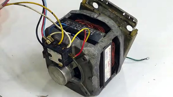
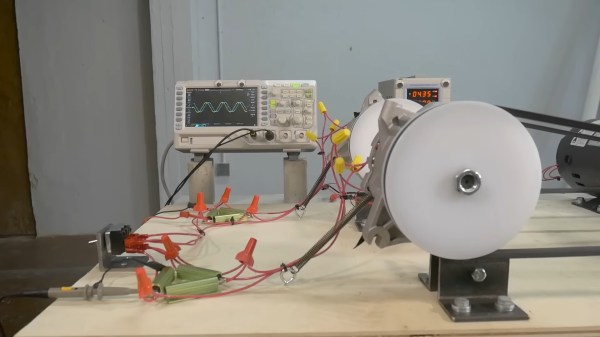
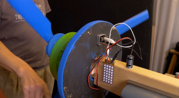
There’s great potential in salvaging a motor from a broken appliance, but so often the part in question is very specific to its application, presenting a puzzle of wires to the experimenter. This was very much the case with older washing machines and other white goods, and while their modern equivalents may have switched to more understandable motors, there are still plenty of the older ones to be had. [Matthias random stuff] sheds a bit of light on how these motors worked, by means of a 1980s Maytag washing machine motor.
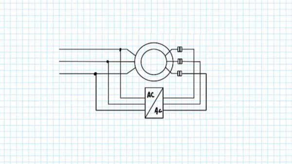
Many of us will be used to old-style induction motors, in which two windings were fed out of phase via a large capacitor. This one doesn’t have a capacitor, instead it has a primary winding and a secondary one with a higher resistance. We’re not quite sure the explanation of the resistance contributing to a phase shift holds water, however this winding is connected in for a short time at start-up by a centrifugal switch. Even better, reversing its polarity reverses the direction of the motor.
The result is a mess of wires demystified, and a mains powered motor with a bit of strength for your projects. We’ve let a few of these motors slip through our fingers in the past, perhaps we shouldn’t have been so hasty.
This is a subject that we’ve looked at in the past.

