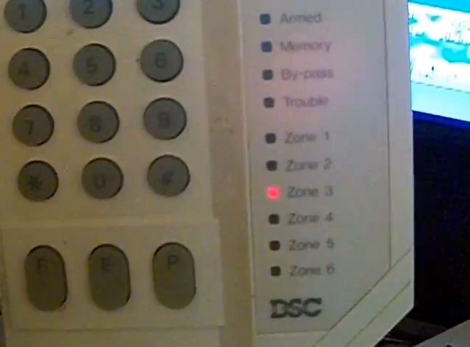
Keypad Uses A PIC’s Built In Capacitance Functionality

[Giorgos Lazaridis’] most recent project was to build a capacitive touch pad. Since he’s using a PIC 16F1937 it will be relatively easy. That’s because it has a 16 channel capacitance sensing module built right in. But there are still some design considerations that make the development a bit touching.

This isn’t the first time he’s worked with capacitance sensing. Through past experience he has found that it is very important to position the microcontroller as close to the button pads as possible. Because of this, the chip is soldered on the back of the PCB used for the keypad itself. Because he’s hand soldering vias, he also used some foam tape to raise the button pads just a bit. This way they will be flush with the acrylic overlay, which cannot sit flat on the board due the via solder joints.

Check out the video after the break to hear [Giorgos] walk us through the project.

Continue reading “Keypad Uses A PIC’s Built In Capacitance Functionality”

Repairing A Broken Microwave Keypad

microwave_keypad_fix

[Alexandre Souza] needed a microwave pretty badly, but he didn’t have a lot of cash on hand. He located one for a great price, but once he got home he found that things weren’t working quite like they should be (Google translation).

After some investigation, he narrowed the problem down to a bad keypad membrane. Unfortunately for him, this model of microwave was never sold in Brazil (who knows how it got there) and the only membrane he could track down had to be shipped in from the US at a cost of $80.

Rather than pay such a high price for a simple membrane, he opted to fix the microwave himself. He dismantled the control panel and thoroughly traced the keypad matrix to get an understanding of which pins toggled which functions. With a piece of protoboard and almost two dozen push buttons in hand, he built his own keypad and wired it directly into the microwave’s control board.

With labels written in marker it might not be the nicest looking thing you have ever seen, but it works a treat and is a great money-saving hack.

Keypad Input Scanning By A 555 Timer

[R-B] designed a 555 timer circuit to scan a keypad. Keypads are common interfaces for small projects and require row and column scanning by a microcontroller. [R-B’s] setup allows you to reduce the number of pins used on the microcontroller to just two. One is an interrupt that is triggered when any of the buttons are pushed, the other reads the frequency from the 555 chip. Each button has its own resistance which alters the frequency of the 555. The microcontroller reads the frequency for 100ms using a timer. The number of timer overflows that occur during that period directly correspond to the button press (five overflows for the numeral 5, zero overflows for the numeral zero).

We usually debounce our button presses for 40 ms, this is more than twice that amount of time but still not a staggering difference. It does make us wonder if you will miss quick button presses? The only really way to know is to try this out yourself. Check out the video after the break and don’t forget to leave a comment with your own experiences in working with the circuit.

Continue reading “Keypad Input Scanning By A 555 Timer”

Building A Security Access Panel

It turns out that hacking together a security keypad is remarkably simple if you know what you’re doing. [Don] needed to add a keypad with an RFID reader on it. He had previously built a USB RFID reader and thought he could integrate those concepts into the new unit.

He once again started with a serial to USB converter and removed the voltage converter IC for later use since he doesn’t need TTL levels for this project. The keypad is a USB product and it turns out there’s a hub inside. With plenty of space inside for the serial converter PCB and a blank spot at the top where he mounted the RFID reader, he adding a few passive components to wire it up and connect it to the hub. The only connection is the original USB cord but the PC will detect both the keypad and the converter.

Knitting Machine Hack By Keypad Emulation

[Travis Goodspeed] and Hackaday alum [Fabienne Serriere] joined forces to develop an alternative interface for a knitting machine. They’re working with the Brother KH-930E machine. We saw [Becky Stern] use the same model by manipulating data on an emulated floppy drive for the device. [Travis] and [Fabienne] went a different route, and are emulating the keypad using an Arduino and a set of transistors.

They started by reverse engineering the keypad matrix using a continuity tester. Once they worked out the column and row layout they connected each to an NPN transistor. The Arduino sketch simulates button presses to set knitting bits for each row, with just one reset button for user input. This can be used to send data from a PC, or as a standalone system. Either way, it’s not only a great way to add functionality to the kitting machine, but a good example of how to interface with the keypad on just about any device.

Playing Hacker With A Toy Vault

[Thomas Cannon] created his own hacking game by adding some circuitry to this toy vault. The original toy uses the keypad to control a solenoid keeping the door shut. He kept the mechanical setup, but replaced the original circuit board with his own ATmega328 based internals. He also added a USB port to the front. The gist of the game is that you plug-in through USB to gain access to the vault’s terminal software. If you can make your way through the various levels of admin access the loot inside will be yours.

PIC Programmable Power Supply

This programmable power supply is the perfect addition to your bench tools. [Debraj Deb], who previously built a whole house power monitor, designed this build around a PIC 18F4520 microcontroller. The desired voltage is set with an attached keypad, resulting in a digital output on the 8-bits of port D. The port connects to another protoboard with an R-2R digital-to-analog converter resulting in the target voltage. A set of transistors amplifies the current and a power transistor then takes care of the final output. After the break you’ll find two videos, the first walks us through the hardware and the second demonstrates the device in action, along with measurements of its performance. This certainly provides a lot more functionality than an ATX power-supply conversion.

Update: A big thanks to [Debraj] who sent us a code package as well as the schematic (PDF) used during testing. We’re having trouble getting the code package up for download right now. Check back later, hopefully we’ll have it up soon.

Continue reading “PIC Programmable Power Supply”