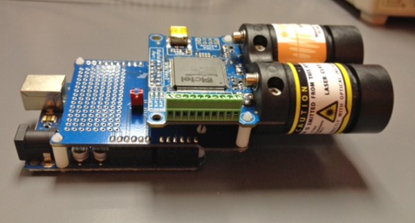
Range finders are amazing tools for doing pretty much anything involving distance calculations. Want to blink some lights when people are nearby? There’s a rangefinder for that. Need to tell how far away the next peak of a mountain range is? There’s a rangefinder for that. But if you’re new to range finders and want one that’s hackable and configurable, look no further than the SF02/F rangefinder with the Arduino shield, and [Laser Developer]’s dive into what this pair can do.
Once the rangefinder and shield have been paired is when the magic really starts to happen. Using USB, the Arduino can instantly report a huge amount of raw data coming from the rangefinder. From there, [Laser Developer] shows us how to put the device into a “settings” mode which expands the capabilities of the rangefinder even more. The data can be dumped into a graph, for example, which can show trends between distance, laser strength, and many other data sets. [Laser Developer] goes one step further and demonstrates how to use this to calculate the speed of light, but from there pretty much anything else is possible as well.
And while you can just buy a rangefinder off the shelf, they are fairly limiting in their features and can cost exponentially more. This is a great start into using a tool like this, especially if you need specific data or have a unique application. But, if laser range finding isn’t for you or if this project is too expensive, maybe this $5 ultrasonic rangefinder will work better for your application.
An irritation-free razor that gives a close shave has been a dream for thousands of years. [Gillette] came close, and with multiple blades came even closer, but all razors today are still just sharpened steel dragged across the skin. This is the 21st century, and of course there’s a concept for a laser razor pandering for your moola. We recently covered the Skarp laser razor and its Kickstarter campaign, and today the campaign has been shut down.
The email sent out to all contributors to the Skarp campaign follows:
Hello,
This is a message from Kickstarter’s Integrity team. We’re writing to notify you that the Skarp Laser Razor project has been suspended, and your pledge has been canceled.
After requesting and reviewing additional material from the creator of the project, we’ve concluded that it is in violation of our rule requiring working prototypes of physical products that are offered as rewards. Accordingly, all funding has been stopped and backers will not be charged for their pledges. No further action is required on your part. Suspensions cannot be undone.
We take the integrity of the Kickstarter system very seriously. We only suspend projects when we find evidence that our rules are being violated.
Regards, Kickstarter Integrity Team
It only took eight hours for the Skarp team to relaunch their crowdfunding campaign on Indiegogo. As of this writing, over 900 people (ostensibly from the 20,000 backers of the original Kickstarter campaign) have pledged to the new campaign.
Although we will never know exactly why Kickstarter suspended the original Skarp campaign, the reason given by the Kickstarter Integrity Team points to the lack of a working prototype, one of the requirements for technology campaigns on Kickstarter. Interestingly, Skarp did post a few videos of their razor working. These videos were white balanced poorly enough to look like they were filmed through green cellophane, a technique some have claimed was used to hide the actual mechanism behind the prototype’s method of cutting hair. A few commenters on the Skarp Kickstarter campaign – and here on Hackaday – have guessed the Skarp prototype does not use lasers, but instead a heated length of nichrome wire. While this would burn hair off, the color of the wire would be a dull red when filmed in any normal lighting conditions. It is assumed the poor quality of the Skarp prototype videos is an attempt to hide the fact they do not have a working prototype.
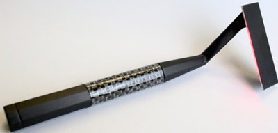
The Skarp laser razor. Source
Skarp’s move to Indiegogo has been lauded by some – mostly in the comments section of the Indiegogo campaign – and has been derided on every other forum on the Internet. Indiegogo is commonly seen as the last refuge of crowdfunding scam artist, but there are a few legitimate reasons why a campaign would choose to go to Indiegogo. Kickstarter is not available for campaign founders in all countries, and for some, debiting a card immediately, instead of after the campaign end like Kickstarter does, is a legitimate crowdfunding strategy.
But for a crowdfunding campaign to be suspended on Kickstarter and immediately move to Indiegogo? This almost never ends well. One of the most famous examples, the Anonabox, had its Kickstarter campaign suspended after it was found the creator was simply rebadging an off-the-shelf router. The Anonabox then moved over to Indiegogo where it raised over $80,000. Already the campaign for the Skarp Laser Razor has raised $135,000 USD from Indiegogo, after having its Kickstarter campaign raised over $4 Million. No, Skarp won’t be one of the most successful technology Kickstarter campaigns of all time. We can only hope it won’t be one of Indiegogo’s most successful campaigns.
At the end of the 19th century, [King Camp Gillette] had the idea of creating a disposable razor blade that didn’t need sharpening. There was one problem with this idea: metallurgy was not yet advanced enough to produce paper-thin carbon steel blades and sharpen them for a close shave. In 1901, [William Nickerson] solved this problem, and the age of disposable razors began.
The Skarp laser razor
This Kickstarter would have you believe there is a new era of beard technology dawning. It’s a laser razor called Skarp, and it’s on track to become one of the most funded Kickstarters of all time. The only problem? Even with relatively good documentation on the Kickstarter campaign, a demo video, a patent, and an expert in the field of cosmetic lasers, only the creators can figure out how it works.
Instead of using technology that has been tried and tested for thousands of years, the Skarp uses a laser to shave hairs off, right at the surface of the skin. You need only look at a billboard for laser hair removal to realize this is possible, but building a laser razor is something that has eluded us for decades. This patent from 1986 at the very least demonstrates the beginnings of the idea – put a laser beam in a handheld package and plunge it into a beard. This patent from 2005 uses fiber optics to send a laser beam to a handheld razor. Like anything out of the sci-fi genre, a laser razor is a well-tread idea in the world of invention.
But Skarp thinks it has solved all of the problems which previously block lasers from finding a place in your medicine cabinet.
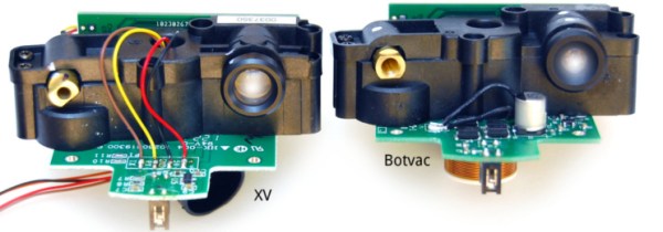
It seems second nature to us and it’s one of the ways we hackers are different from the larger population… sometimes we absolutely insist on buying something that is already broken. Which is where we join [Anton] as he reverse engineers, debugs, and repairs a broken Neato Botvac’s LiDAR system all in the name of having clean floors at a fraction of the cost.
Now keep your head on a swivel ’cause along the way [Anton] has the all-too familiar point in his repair where he puts the original project on hold while he makes a specialized tool he needs to finish the job. It’s hard to tell which is more impressive: turning a laptop webcam into a camera capable of clearly viewing bond wires and (wait for it!) where they are attached on the Silicon, or that he (yeah, we were making a comparison…member?) went straight back to solving the original problem. [Anton] did split this project into two separate blog posts, the first one is linked above and it’s not until the second post that he fixes the original problem. Perhaps there was a bit of scope creep, which was the reason for the separate blog entries? At any rate, [Anton] does a great job documenting the process along with what he calls some ‘juicy pictures’ and you can see a few of them after the break.
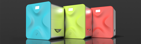
Almost exactly two years ago, news of a great revolution in 3D printing carried itself through blogs and tech columns. Patents were expiring, and soon the ‘squirting filament’ printers would be overtaken by a vastly better method: selective laser sintering. In the last two years, the market has been markedly silent on the possibilities of SLS technology, until now, at least. Today, Sinterit is launching their first printer. It’s an SLS printer that builds objects by fusing nylon powder with a laser, producing things with much better quality than filament-based printers.
The Sinterit Lisa is a true laser sintering printer, able to create objects by blasting nylon powder with a 5W laser diode. Inside this box that’s about the same size as a laser printer is a CoreXY mechanism to move the laser diode around, heated pistons, cylinders, feed bed and print bed for keeping the print volume at the right temperature and the top layer perfectly flat. The layer thickness of the printer goes down to 0.06 mm, and the maximum print size is 13 x 17 x 13 cm. Material choice is, for now, limited to black PA12 nylon but other materials are being tested.
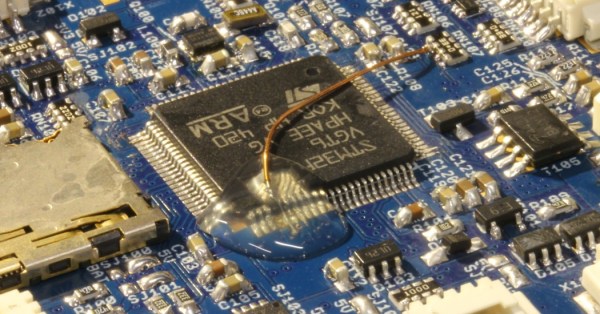
[Carsten] messed up. He was soldering an ARM CPU onto a quadcopter board in haste, failed to notice that the soldering iron was turned up to eleven, and pulled some of the traces up off the PCB. In the process of trying to fix that, he broke three pins off of the 100-pin CPU. The situation was going from bad to worse.
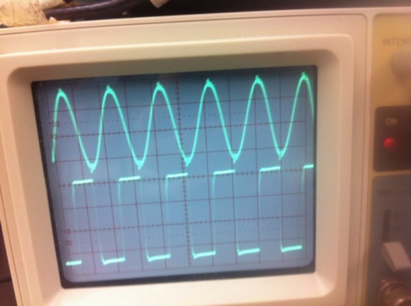
[Carlos] needed an ADC with a 50 nanosecond sample period for his laser lab, that’s 20Msps! (20 million samples a second). While in recent years, commodity ADCs reaching into the low GSPS have become available, integrated acquisition systems are still somewhat expensive. So [Carlos] decided to do what every good hacker does, and built his own solution. His project post pretty much just links to a whitepaper he wrote (PDF) so we’ll try and boil it down for you:
In order to simplify development [Carlos] borrowed a technique commonly used in the first era of digital oscilloscopes, Equivalent Sampling Time.
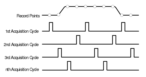
The figure to the right is from the TDS460 manual. While it may seem counter intuitive to those only familiar with modern scopes, the TDS460 achieved a 400MHz bandwidth using a 100MSPS ADC. In order to achieve this the scope acquires a single trace in multiple cycles, each time offsetting the acquisitions as shown and combining the result.
In this way, early digital scope developers could sidestep the limitations of the available ADCs to achieve a higher effective bandwidth. However there is of course one catch: the technique only works for periodic signals.
This was fine for [Carlos] who implemented a technique on a Cypress PSoC 4, which provides analog FPGA-like functionality. By offsetting the ADC trigger he has able to achieve an EST of 48MHz using a ADC sampling at 1MHz. If you want a little help getting into PSOC 4 yourself, check out the guide that [Bil Herd] made.
Neat hack [Carlos] and we hope to hear more about your laser lab in the future.