Summer And Tailgating DIY Projects Roundup

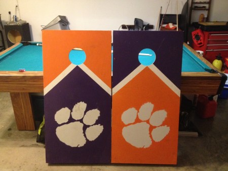
tiger-paw-cornhole

If you live in the Southeastern United States as I do, you’ve probably been enjoying a summer of grilling out and going to the beach or lake. You’re also may be getting ready to enjoy football tailgating season, especially if you attend or live near a college town. Here’s a couple of DIY items that should be welcome at any outdoor event you choose to attend.

How to Make a Cornhole Board:

cornhole toss board

Although there are no LEDs or an Arduino on this one (we’d love to see your pimped boards in the comments), these instructions should work well for making your basic cornhole set. Of course you can always add some folding legs to it, but they fit together pretty well as is.  As for the paint, there are many ways to do this, but check out the pic after the break to see the laser-cut stencil that the Tiger Paw in the first picture was made from.  Thanks [Essam]!

PVC Ladder Toss Set:

ladder toss game PVC

These instructions should tell you all you need to make your own ladder toss (or whatever less-PC name you decide call it). As for the golf ball “bolas,” you’ll have to figure out how to put a hole in the middle of them. This technique (as seen in a links post earlier) should cover it, but best to be careful that you’re not plunging into a liquid-core ball. Eye protection is recommended.

LED Glow Cubes:

solar LED glow cube

Although not a traditional tailgate item, these glowing solar LED cubes could serve as an alternative to the normal LED path lights. What’s in these instructions is how to simply take the parts source, a solar path light, apart and insert it into a translucent cube. We could see this made with several different colored LEDs and an Arduino for some other cool effects.  A logo of your favorite team could be added with a laser cutter or CNC router for tailgate use. Continue reading “Summer And Tailgating DIY Projects Roundup”

POV Bike Wheels With The MSP430

Being an intern a Texas Instruments isn’t all fun and games, but from [George], [Valerie], and [Ryan]’s TI intern design project, it sure looks like it. They built a persistence of vision display for a bicycle using the ever popular MSP430 Launchpad board.

The team of interns created a POV display by combining the power of the TI Launchpad with a row of 32 RGB LEDs soldered onto a booster pack. Once the whole circuit is fastened securely to the bike wheel, a hall effect sensor mounted to the bike frame allows the MSP430 to detect how fast it is going. From there, it’s just a matter of flashing LEDs at the right time to create a stationary display inside a rotating wheel.

Although the display will theoretically work with just one Launchpad/Booster pack combo, the team decided to use three of these circuits, totaling 96 LEDs per wheel, to create a really nice RGB display. The video (available after the break) shows a little bit of flicker but this is an artifact of the camera. In real life, the POV bike wheel display is simply stunning.

Continue reading “POV Bike Wheels With The MSP430”

Developing A Better Way To Control 10,000 LEDs

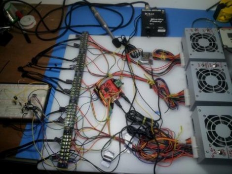
The SoundPuddle project drives thousands of LEDs based on audio input. The team is working on a replacing the controller for this wire-filled setup with something more robust. They took the mess seen above to the Apogaea Festival and were plagued by loose wires and unreliable communications due to noise and interference. The aim of the new system is to reliably control up to 10,000 LEDs.

The red PCB seen at the center of the rats-nest is a Papilio FPGA board. They still want to use it to drive the installation, but a new hardware interface is necessary. The solution is to design what they call a megawing (wings are to Papilio as shields are to Arduino).  The LEDs will be in RGB strip form, so one of the requirements is to supply enough connectors to drive 16 channels of SPI devices. The wing will also include the 48V power source and connectors for the condenser microphone that serves as an input for the SoundPuddle. There are also two other options for audio input, one via a Bluetooth module (which can double as a control device) and the other via MIDI.

After the break you can see a lighting demo. Be ready with the volume controls as most of the sounds used in the test are quite annoying.

Continue reading “Developing A Better Way To Control 10,000 LEDs”

Writing On LEDs With A Laser Pointer

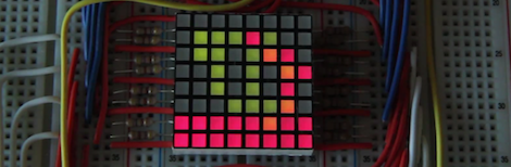
After [Ch00f] got his hands on an 8×8 LED display, he didn’t make a 64-pixel video game or VU meter. He made a laser doodler, allowing him to draw on this display with only a laser pointer.

Using LEDs as light sensors is nothing new; [Forrest Mims III] discovered that LEDs can also detect light way back in the late 60s. [Ch00f] played around with this concept before creating a circuit that uses an LED as both a light emitter and sensor that reacts to the ambient brightness.

[Ch00f]’s laser doodler takes this phenomena and applies it to an Adafruit bicolor LED matrix. When a light shines on an individual pixel in the display, the ATMega48 senses the current and turns that pixel on. Since this these pixels have two colors, [Ch00f] used a latch circuit and a button to cycle between what color the ‘Mega writes to the display.

In the video after the break, [Ch00f] shows off his display by having the LEDs light up in response to a laser pointer. It may be a bit small, but we can see a lot of potential for something like this as a gigantic art installation.

Continue reading “Writing On LEDs With A Laser Pointer”

The Many Iterations Of [Joe’s] PCB Business Card

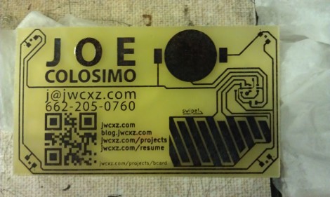
[Joe Colosimo] is putting on a show with his PCB business card project. The idea isn’t new, but his goal is to keep it simple and undercut the cost of all other PCB cards he’s seen. This is the third generation of the board design, and he’s just waiting on some solder mask solution before he tries running it through the reflow oven.

The first two prototypes used some through-hole parts. Notably, the battery was to be positioned in a circular cut-out and held in place by a metal strap and some bare wires. But he couldn’t quite get it to work right so this design will transition to a surface-mount strap for one side, and the large circular pad for the other. At each corner of the board there is a footprint for an LED. He tried milling holes in the board to edge-light the substrate. Now he just mounts the LED upside down to give the board a blue glow. The LEDs are driven by an ATtiny10 microcontroller which takes input from the touch sensor array at the bottom right.

He etched a QR code on the board which seems to work better than the milled QR experiments we saw back in April. The link at the top point’s to [Joe’s] main page on the card. Don’t forget to follow the links at the bottom which cover each part of the development more in-depth.

[Thanks Skitchin]

Fabricating Headlights For An F250

The amount of time that is going into these custom headlights is just staggering. [Mcole254] is working on his brother’s truck, replacing the stock headlights with High-Intensity Discharge (HID) lamps and rolling some nice LED features into the mix while he’s at it.

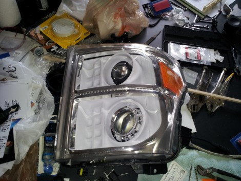
The build starts by removing and disassembling the stock headlight assembly. In order to get the enclosure apart he heated it in the oven until the glue was softened and the parts could be pried apart. The goal is to replace the reflectors with an assembly that suits the new lamps and LEDs. Above you can see the white pieces which were vacuum formed from a mold that [Mcole254] made from wood and PVC. He tried several iterations using his home-made vacuum former but couldn’t get the definition he really wanted. The most recent posts from him show some massive 3D printed parts that will be used instead.

While inside he added a line of amber LEDs for the turn signal. You can seem them mounted along the silver strip between the upper and lower reflectors. A demo of those super bright additions is embedded after the break.

Continue reading “Fabricating Headlights For An F250”

Levitating Lightbulb Does It All With No Wires

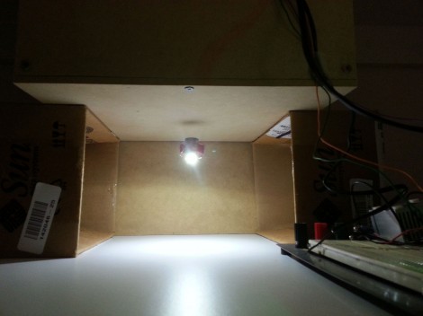
It would be really fun to do an entire hallway of these levitating wireless lights. This a project on which [Chris Rieger] has been working for about six months. It uses magnetic levitation and wireless power transfer to create a really neat LED oddity.

Levitation is managed by a permanent magnet on the light assembly and an electromagnetic coil hidden on the other side of the top panel for the enclosure. That coil uses 300 meters of 20 AWG wire. A hall effect sensor is used to provide feedback on the location of the light unit, allowing the current going to the coil to be adjusted in order to keep the light unit stationary. When working correctly this draws about 0.25A at 12V.

Wireless power transfer is facilitated by a single large hoop of wire driven with alternating current at 1 MHz. This part of the system pulls 0.5A at 12V, bringing the whole of the consumption in at around 9 Watts. Not too bad. Check out [Chris’] demo video embedded after the break.

A similar method of coupling levitation with power transfer was used to make this floating globe rotate.

Continue reading “Levitating Lightbulb Does It All With No Wires”