Building giant LED walls comes with a serious set of challenges. Whether they lie in power, cable routing, or just finding a way to clock out data fast enough for all the pixels, it takes some doing to build a decent sized display. [Phill] wanted a statement piece for the office, so rolled up his sleeves and got to work.
The build uses P5 panels, which we’ve seen used before on a smaller scale. Initial testing was done with a Raspberry Pi 3, which started to run out of grunt when the build reached 28 panels. The refresh rate was slow, and anything with motion looked messy. At that point, a dedicated driver was sourced in order to handle the full 48-panel display. Other challenges involved dealing with the huge power requirements – over 170 amps at 5 volts – and building a frame to hold all the panels securely.
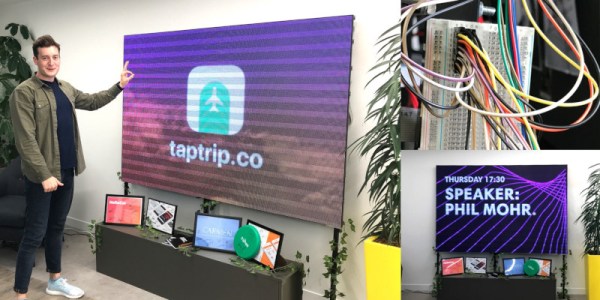
The final product is impressive, standing 2 meters wide and 1.2 meters high. Resolution is 384 x 256. With a Mac Mini running video into the display through the off-the-shelf driver, all manner of content is possible. [Phill] even whipped up a Slack channel for users to send GIFs and text messages to the display. Naturally, we’re sure nobody will take advantage of this functionality.
If you’ve got your own giant LED wall, and you’re dying to tell us about it, make sure you get in touch. Video after the break.
Continue reading “Big Ol’ LED Wall Looks Cool, Can Draw Over 170 Amps”