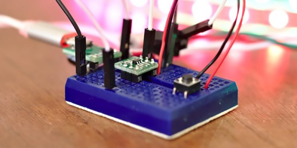
Low-energy ESP8266-based Board Sleeps Like A Log Until Triggered

Given the popularity of hacking and repurposing Amazon Dash buttons, there appears to be a real need amongst tinkerers for a simple “do something interesting on the internet when a button is pressed” device. If you have this need but don’t feel like fighting to bend a Dash device to your will, take a look at [Kevin Darrah]’s trigBoard instead.

The trigBoard is a battery-powered, ESP8266-based board that includes some clever circuitry to help it barely sip power (less than one microamp!) while waiting to be triggered by a digital input. This input could be a magnetic reed switch, push button, or similar, and you can configure the board for either normally open or normally closed switches.

The clever hardware bits that allow for such low power consumption are explained in [Kevin]’s YouTube video, which we’ve also embedded after the break. To summarize: the EPS8266 spends most of it’s time completely unpowered. A Texas Instruments TPL5111 power timer chip burns 35 nanoamps and wakes the ESP8266 up every hour to check on the battery. This chip also has a manual wake pin, and it’s this pin – along with more power-saving circuitry – that’s used to trigger actions based on the external input.

Apparently the microcontroller can somehow distinguish between being woken up for a battery check versus a button press, so you needn’t worry about accidentally sending yourself an alert every hour. The default firmware is set up to use Pushbullet to send notifications, but of course you could do anything an EPS8266 is capable of. The code is available on the project’s wiki page.

The board also includes a standard micro-JST connector for a LiPo battery, and can charge said battery through a micro-USB port. The trigBoard’s full schematic is on the wiki, and pre-built devices are available on Tindie.

[Kevin]’s hardware walkthrough video is embedded after the break.

Continue reading “Low-energy ESP8266-based Board Sleeps Like A Log Until Triggered”

Trials And Tribulations In Sending Data With Wires

When working on a project that needs to send data from place to place the distances involved often dictate the method of sending. Are the two chunks of the system on one PCB? A “vanilla” communication protocol like i2c or SPI is probably fine unless there are more exotic requirements. Are the two components mechanically separated? Do they move around? Do they need to be far apart? Reconfigurable? A trendy answer might be to add Bluetooth Low Energy or WiFi to everything but that obviously comes with a set of costs and drawbacks. What about just using really long wires? [Pat] needed to connect six boards to a central node over distances of several feet and learned a few tricks in the process.

When connecting two nodes together via wires it seems like choosing a protocol and plugging everything in is all that’s required, right? [Pat]’s first set of learnings is about the problems that happen when you try that. It turns out that “long wire” is another way to spell “antenna”, and if you happen to be unlucky enough to catch a passing wave that particular property can fry pins on your micro.

Plus it turns out wires have resistance proportional to their length (who would have though!) so those sharp square clock signals turn into gently rolling hills. Even getting to the point where those rolling hills travel between the two devices requires driving drive the lines harder than the average micro can manage. The solution? A differential pair. Check out the post to learn about one way to do that.

It looks like [Pat] needed to add USB to this witches brew and ended up choosing a pretty strange part from FTDI, the Vinculum II. The VNC2 seemed like a great choice with a rich set of peripherals and two configurable USB Host/Peripheral controllers but it turned out to be a nightmare for development. [Pat]’s writeup of the related troubles is a fun and familiar read. The workaround for an incredible set of undocumented bad behaviors in the SPI peripheral was to add a thick layer of reliability related messaging on top of the physical communication layer. Check out the state machine for a taste, and the original post for a detailed description.

The Smaller, Tinier Arduino Platform

While many of the Arduino platforms are great tools for gaining easy access to microcontrollers, there are a few downsides. Price and availability may be the highest on the list, and for those reasons, some have chosen to deploy their own open-source Arduino-compatible boards.

The latest we’ve seen is the Franzininho, an Arduino Gemma-like board that’s based on the ATtiny85, a capable but tiny microcontroller by Atmel in a compact 8-pin configuration. This board has everything the Gemma has, including a built-in LED and breakout pins. One of the other perks of the Franzininho over the Gemma is that everything is based on through-hole components, making the assembly much easier than the surface mount components of the Gemma.

It’s worth noting that while these boards are open source, the Arduinos are as well. It’s equally possible to build your own 100% identical Arduino almost as easily. If you want more features, you can add your own by starting from one of these platforms and do whatever you want with it, like this semi-educational Atmel breakout board.

Thanks to [Clovis] for the tip!

General Purpose I/O: How To Get More

The first program anyone writes for a microcontroller is the blinking LED which involves toggling a general-purpose input/output (GPIO) on and off. Consequently, the same GPIO can be used to read digital bits as well. A traditional microcontroller like the 8051 is available in DIP packages ranging from 20 pins to 40 pins. Some trade the number of GPIOs for compactness while other devices offer a larger number of GPIOs at the cost of complexity in fitting the part into your design. In this article, we take a quick look at applications that require a larger number of GPIOs and traditional solutions for the problem.

A GPIO is a generic pin on an integrated circuit or computer board whose behavior, including whether it is an input or output pin, is controllable by the user at runtime. See the internal diagram of the GPIO circuit for the ATmega328 for reference.

Simply put, each GPIO has a latch connected to a drive circuit with transistors for the output part and another latch for the input part. In the case of the ATmega328, there is a direction register as well, whereas, in the case of the 8051, the output register serves as the direction register where writing a 1 to it sets it in output mode.

The important thing to note here is that since all the circuits are on the same piece of silicon, the operations are relatively fast. Having all the latches and registers on the same bus means it takes just one instruction to write or read a byte from any GPIO register.
Continue reading “General Purpose I/O: How To Get More”

It’s UNIX. On A Microcontroller.

It’s difficult to convey in an era when a UNIX-like operating system sits in your pocket, how there was once a time when the mere word was enough to convey an aura of immense computing power. If you ran UNIX, your computer probably filled a room, and you used it for Serious Stuff rather than just checking your Twitter feed. UNIX machines may still perform high-end tasks, but Moore’s Law has in the intervening years delivered upon its promise, and your phone with its UNIX-like OS is far more powerful than that room-sized minicomputer of the 1970s. A single chip for a few cents can do that job, which begs the question: just how little do we need to run UNIX today? It’s something [Joerg Wolfram] could advise you upon, because he’s got a functional UNIX running on a microcontroller.

Of course, the UNIX in question is not exactly the same as the one you’d find on a supercomputer, either in the 1970s or now. Mini UNIX is a minimalist version of the operating system developed by [Heinz Lycklama] at Bell Labs four decades ago. It gives you a complete UNIX V6 system for the DEC PDP-11, but which needs only 56K of RAM, and no MMU. Emulating a PDP-11 on an STM32 microcontroller allows it to run happily, and while it’s not the most minimalist of microcontrollers it’s still a pretty cheap part upon which to run UNIX.

It’s doubtful whether a 1970s version of an operating system on a commodity microcontroller will take the world by storm, but that’s hardly the point of such a neat hack. It’s certainly not the first time we’ve seen similar work, though this PIC32 offering has a little more in the way of resources to offer.

Header image: Golonlutoj [CC BY-SA 3.0].

Ask Hackaday: How Do You DIY A Top-Octave Generator?

One of the great joys of Hackaday are the truly oddball requests that we sometimes get over the tip line. Case in point: [DC Darsen] wrote in with a busted 1970s organ in need of a new top-octave generator, and wondered if we could help. He had found a complicated but promising circuit online, and was wondering if there was anything simpler. I replied “I should be able to get that done with a single Arduino” and proceeded to prove myself entirely wrong in short order.

So we’re passing the buck on to you, dear Hackaday reader. Can you help [DC Darsen] repair his organ with a minimum amount of expenditure and hassle? All we need to do is produce twelve, or maybe thirteen, differently pitched square waves simultaneously.

Continue reading “Ask Hackaday: How Do You DIY A Top-Octave Generator?”

Investigating The Tiny Salvaged UPS From A Lightbulb

Recently I had the opportunity to do a teardown of a battery-backed LED bulb, and found some interesting details on how the device operated. Essentially, the bulb contained a low voltage DC uninterruptible power supply that would automatically switch between AC power and internal battery as needed. The implications of this seemed pretty exciting. For around $12 at big box retailers, this little bulb could be a cheap and convenient solution for providing fault tolerant power to microcontrollers and other low-power devices.

The teardown was a runaway success, with quite a bit of discussion of the UPS idea specifically. Some people hated it, others loved it. But as we’ve come to expect from Hackaday readers, the comments from both sides of the aisle contained keen observations and invaluable real-world experience. From the safety of the device to the accuracy of the manufacturer’s claims, it seems like every element of the product was addressed.

I had ended the teardown with a promise that I’d continue experimenting with the tiny salvaged UPS, but even if I hadn’t, with so much feedback it seemed revisiting the subject was all but a necessity. It this little UPS really viable? Is it too dangerous to safely implement in your project? Will the thing just blow up?

So with your comments as a guide, and free of the somewhat restrictive teardown format, I set out to conduct a more thorough investigation of this little circuit that caused so much debate last month. It’s not all good news, but it’s not in the trash either. Not yet, anyway.

Continue reading “Investigating The Tiny Salvaged UPS From A Lightbulb”