Plexitube Owl Clock Watches You Sleep

Wait, plexitube? Is that a typo? Surely we mean Nixie tubes!

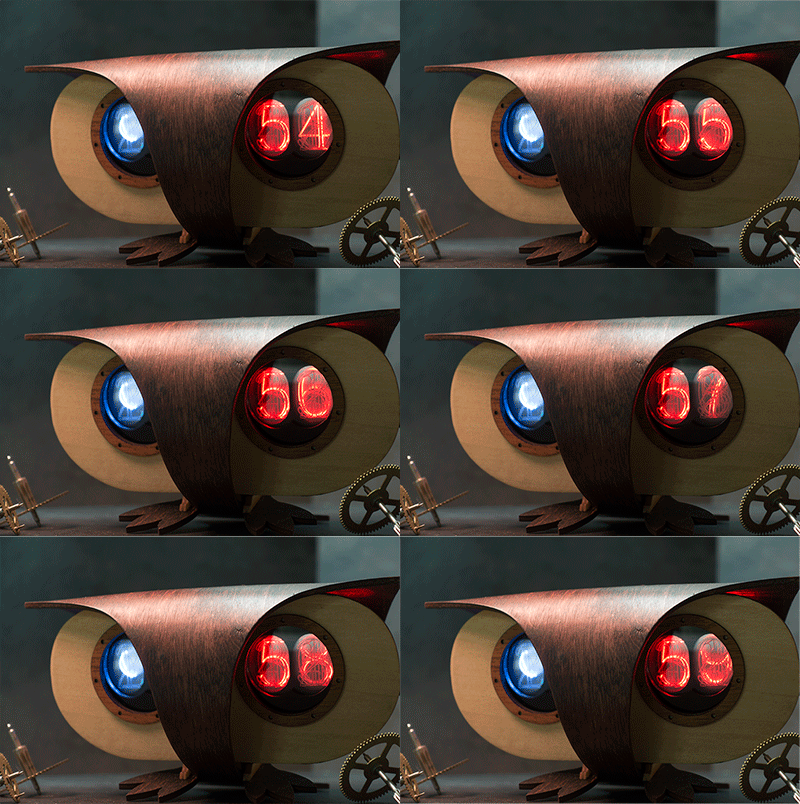
For a Christmas project [Kurt] wanted to build some owl-inspired clocks — with bit of a retro feel. Given the complexities of finding and using actual Nixie tubes, he went with an alternative — a Plexitube.

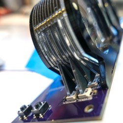
lightguidescloseup
Closeup of Plexitube

Plexitubes look like futuristic Nixie tubes. They can have different stylized numbers. They’re crisp, they’re bright, and they are completely customizable. They’re made of edgelit acrylic! By laser etching the design onto pieces of acrylic and feeding LED light into the edge, very much like how a light-pipe works, it’s possible to have a neon-light effect — using nothing more than plastic and some LEDs.

He designed custom PCBs for the project, with SMD LEDs for the plexitubes. Making use of a laser cutter, he designed the actual owl to be made out of lightly formed wood cutouts — the entire thing looks absolutely fantastic.

As far as “Nixie tube” clocks this has gotta be one of the most aesthetically pleasing ones we’ve seen in a while, but if you’re looking for an all-out-Nixietube-extravaganza… take a look at this whopping thirteen tube clock.

[Thanks for the tip Lawrence!]

Nixie Clock Uses Ingenious Software RTC

There’s something about Nixie Tube Clocks that keeps drawing hackers to build their own iterations, even if its been done a gazillion times before. Their depleting supply, and the high voltage drivers to control them, makes it all the more interesting. [Pete Mills], a veteran of several interesting projects, many of which we have featured here, is no exception and decided to build his own version of a Nixie Tube Clock, but with several nifty features.

To put it in a nut shell, his Clock uses Nixie tubes for display, has USB serial communication, temperature measurement, AC frequency measurement, time and date keeping with a software based RTC, software driven boost converter for the 175V DC nixie tube supply and a windows app for clock configuration.

The software based time keeping is pretty interesting. It is essentially a method to calibrate the crystal to more closely match real time, and some code to keep track of the time and date.  This obviously leads to a reduction in components and the spin-offs that comes with that; increased reliability, cost reduction, real estate savings. The RTC code can easily be ported to other clock projects irrespective of the display used. Besides keeping track of time and date, it can also account for leap years, and report the day of the week. A zero-crossing detector connected to the low-voltage transformer supply that powers the clock can also be used as an alternative way of keeping time.

When connected to a serial console over UART, the clock can report back many variables depending on the queries it receives. The high voltage DC needed to drive the Nixie tubes is generated using a simple boost converter controlled by the micro controller. An important “gotcha” that [Pete] deduced after blowing off several fuses, was to disconnect the micro controller port connected to the PWM timer and explicitly set it to output low via software. There’s a couple of other issues that he ran into – such as board layout, power supply, incorrect pullups – that make for interesting reading. The clock enclosure is still work in progress, but [Pete] hopes to get it done sometime soon.

He also wrote a Windows application – Nixie Clock Communicator – to help with time setting and calibration. Finally, he describes in detail the process of calibrating the clock’s software based RTC. Based on his calculations, the clock will drift by about 48 seconds over an 8 month period. Since he will be adjusting for DST much sooner than that, his clock ought to be off from correct time by not more than a minute at any given time. Not bad for a clock that does not use a dedicated RTC chip. [Pete] still has some of the prototype boards to give away if someone is interested. If you’d rather build it yourself from scratch, [Pete] has posted the software code, schematics and PCB, and a BoM.

Hacklet 37 – Nixie Projects

Nothing quite beats the warm glow of a tube. What better way to enjoy that glow than to use it to read numbers? Nixie tubes were created by Haydu Brothers Laboratories, and popularized by Burroughs Corp in 1955. The name comes from NIX I – or “Numeric Indicator eXperimental No. 1”. By the mid 1970’s, seven segment LED’s were becoming popular and low-cost alternatives to Nixies, but they didn’t have the same appeal. Nixie tubes were manufactured all the way into the 1990’s. There’s just something about that tube glow that hackers, makers, and humans in general love. This week’s Hacklet highlights the best Nixie (and Nixie inspired) projects on Hackaday.io!
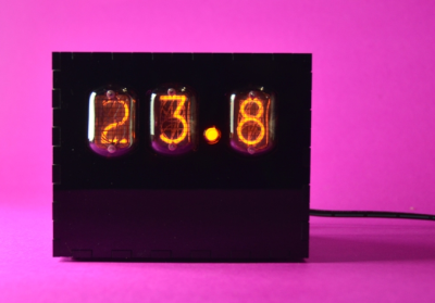
temperatureDisplayWe start with [Sascha Grant] and Nixie Temperature Display. [Sascha] mixed an Arduino, a Dallas DS18B20 Temperature sensor, and three IN-12A Nixie tubes to create a simple three digit temperature display. We really love the understated laser-cut black acrylic case. An Arduino Pro Micro reads the Dallas 1-wire sensor and converts the temperature to BCD. High voltage duties are handled by a modular HV power supply which bumps 9V up to the required 170V.  Controlling the Nixie tubes themselves are the classic K155ID1 BCD to decimal converter chips – a favorite for clock builders.
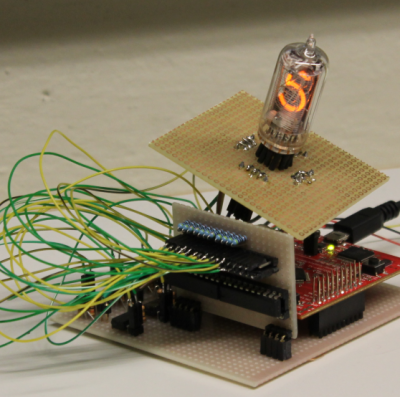
 

driverNext up is [Christoph] with Reading Datasheets and Driving Nixie Tubes. Chips like the K155ID1, and the 74141 make driving Nixie tubes easy. They convert Binary Coded Decimal (BCD) to discrete outputs to drive the cathodes of the Nixie. More importantly, the output drivers of this chip are designed to handle the high voltages involved in driving Nixie tubes. These chips aren’t manufactured anymore though, and are becoming rare. [Christoph] used more common parts. His final drive transistor is a MPSA42 high voltage NPN unit. Driving the MPSA42’s is a 74HC595 style shift register. [Christoph] used a somewhat exotic Texas Instruments TPIC6B595 with FET outputs, but any shift register should work here. The project runs on a Stellaris Launchpad, so it should be Arduino compatible code.
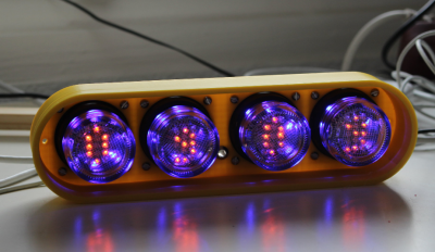
fixietube[Davedarko] has the fixietube clock. Fixietube isn’t exactly a Nixie. It’s an LED based display inspired by Nixie tubes. Modern amber LEDs aren’t quite the same as classic Nixies, but they get pretty darn close. [Dave] designed a PCB with a 3×5 matrix of LEDs to display digits. A few blue LEDs add a bit of ambient light. The LEDs are driven with a 74HC595 shift register. The entire assembly mounts inside a tiny glass jam jar, giving it the effect of being a vacuum tube. The results speak for themselves – fixietubes certainly aren’t Nixies, but they look pretty darn good. Add a nice 3D printed case, and you’ve got a great project which is safe for anyone to build.
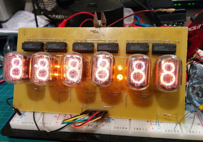
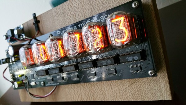
openNixieFinally, we have [Johnny.drazzi] with his Open Nixie Clock Display. [Johnny] has been working on Open Nixie for a few years. The goal is to create a Nixie based clock display which can be driven over the SPI bus. So far, [Johnny] has 6 Russian IN-12 tubes glowing with the help of the ubiquitous K155ID1 BCD to decimal converter. The colons of the clock are created with two INS-1 neon indicators. [Johnny] spends a lot of time analyzing the characteristics of a Nixie tube – including the strike voltage, and steady state current. If you’re interested in building a Nixie circuit yourself, his research is well worth a read!

Not satisfied? Want more Nixie goodness? Check out our Nixie tube project list!

That’s about all the time we have for this week’s Hacklet. As always, see you next week. Same hack time, same hack channel, bringing you the best of Hackaday.io!

nixieclock

Simple And Elegant Single Digit Nixie Tube Clock

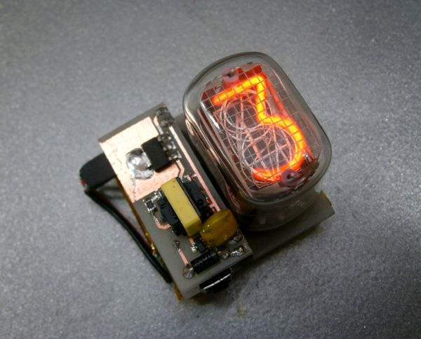
We’ve seen a few Nixie projects around here before, but this one might be the simplest yet. [Pinomelean] designed this simple nixie tube clock with just a handful of components.

The Nixie tube chosen for the project is an IN-12a. This tube can be purchased for around just four dollars. It is capable of displaying one digit at a time, zero through nine. Since the tube can only display one digit at a time, the clock is programmed to flash each digit of the current time one by one. There is a longer pause in between each cycle to make it easier to tell when the cycle begins and ends.

The system is broken into two main components. The first is the clock circuit. The clock runs off a PIC microcontroller with a 4MHz crystal. All of the logic is performed via the PIC and only a handful of other components are required. This includes some resistors and capacitors as well as a few high voltage SMD transistors to control the Nixie tube. [Pinomelean] has made this PCB design available so anyone can download it and make their own clock.

The second component to the clock is the power supply. The system is powered by a lithium-ion rechargeable battery, but [Pinomelean] notes that it can also be powered with USB. The lower voltage works well for the microcontroller, but the Nixie tube needs a higher voltage. [Pinomelean] built his own high voltage supply using components scavenged from an old disposable camera. This power supply board design is also made available for download, but it plugs into the main board so you can use another design if desired.. Check out the demo video below to see it in action. Continue reading “Simple And Elegant Single Digit Nixie Tube Clock”

Nixies And Raspis For A Modern Vintage Calculator

There are a few very rare and very expensive calculators with Nixie tube displays scattered about calculator history, but so far we haven’t seen someone build a truly useful Nixie calculator from scratch. [Scott] did just that. It’s a complete, fully-functional electronic calculator with all the functions you would expect from a standard scientific calculator.

The calculator uses IN-12 Nixies, the standard for anyone wanting to build a clock or other numerical neon discharge display. Each Nixie is controlled by a K155D driver chip, with the driver chip controlled by an I2C IO expander.

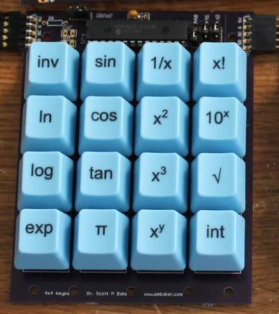
The keypad is where this gets interesting; electronics are one thing, but electromechanicals and buttons are a completely new source of headaches. [Scott] ended up using Cherry MX Blue switches, one of the more common switches for mechanical keyboards. By using a standard keyboard switch [Scott] was able to get custom keycaps made for each of the buttons on his calculator.

The brains of the calculator is a Raspberry Pi, with the I2C pins going off to listen in on the several IO expanders on the device. A Raspi might be a little overkill, but an Internet-connected calculator does allow [Scott] to send calculations off to WolframAlpha, or even the copy of Mathematica included in every Pi.

[Scott] has put his project up on Kickstarter. Videos below.

Continue reading “Nixies And Raspis For A Modern Vintage Calculator”

World’s Largest “Nixie” Clock At World Maker Faire

World Maker Faire was host to some incredible projects. Among the favorites was Nixie Rex [YouTube Link]. Nixie Rex is actually a Panaplex display, since it’s glow comes from 7 planer segments rather than 10 stacked wire digits. One thing that can’t be contested is the fact that Rex is BIG. Each digit is nearly 18 inches tall!

Nixie Rex was created by [Wayne Strattman]. Through his company Strattman Design, [Wayne] supplies lighting effects such as plasma globes and lightning tubes to the museums and corporations. Nixie Rex’s high voltage drive electronics were created by [Walker Chan], a PHD student at MIT. Believe it tor not the entire clock runs on an ATmega328P based Arduino. The digits are daisy chained from the arduino using common Ethernet cables and RJ45 connectors. A Sparkfun DS1307 based real-time clock module ensures the Arduino keeps accurate time.

[Wayne] and Rex were located in “The Dark Room” at Maker Faire, home to many LED and low light projects. The dim lighting certainly helped with the aesthetics, but it did make getting good photos of the clock difficult. Long time Hackaday tipster [Parker] graciously provided us with a size reference up above.

Click past the break to see a closeup of that awesome cathode glow, and a video of the Nixie Rex  in action.

Continue reading “World’s Largest “Nixie” Clock At World Maker Faire”

The State-Based Nixie Multimeter

state

Instead of numbers the IN-15A Nixie tube has symbols, specifically n, μ, P, -, +, m, M, k, Π, and %. The related IN-15B Nixie has letters: A, F, H, Hz, Ω, S, V, and W. These should look familiar to you. [kittan] decided it would be really cool to have a Nixie-equipped multimeter, and since he’s going retro fabulous anyway, he might as well make his multimeter controllerless, with discrete logic and comparator ICs. It’s a state-based Nixie multimeter, and it’s going to be freakin’ awesome.

The basic plan of the multimeter is a precision 1V voltage reference, a bunch of opamps, and a ton of resistors to form a ladder All the opamps in each decade are XOR’d together, so when one of the ten comparators for each decade stage is tripped, only one number will display on the (numeric) Nixie tube.

With a reasonable plan for measuring a voltage, it’s not too hard to expand the design for other measurements. V=IR, so with a constant current, V=R. The same equation can be used with a fixed resistance to determine current. Capacitance can be measured by comparing the change in charge of a known capacitor. Inductance, conductance, power, and frequency are all planned for this monster of a multimeter.

The initial PCB design is completed (and shown above) and it’s theoretically possible to do on a single-sided board with a minimum of jumpers. An amazing project, and even though you could probably find a similar, ancient meter in a trash heap or on a collector’s shelf, this is by far one of the best Nixie projects we’ve ever seen.