FPGA Rescues Scope From The Dumpster

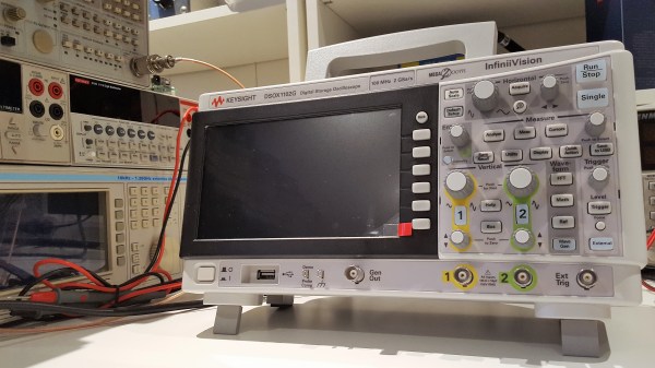
I’m always on the lookout for a quality addition to my lab that would respect my strict budget. Recently, I’ve found myself pushing the Hertz barrier with every other project I do and hence desperately wanted a high bandwidth scope. Unfortunately, only recently have 70 MHz to 100 MHz become really affordable, whilst a new quad channel oscilloscope in the 500 MHz to 1 GHz range still costs a fortune to acquire. My only option was to find an absolute miracle in the form of an old high bandwidth scope.

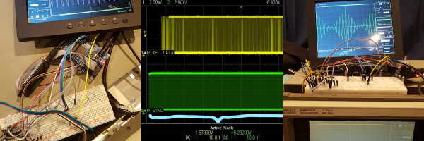
It seemed the Gods of Hand Me Down electronics were smiling upon me when I found this dumpster destined HP 54542C. It appeared to be in fairy good shape and was the Top Dog in its day. But something had to be broken right? Sure enough, the screen was clearly faulty and illegible. Want to know how I fixed it? Four letters: FPGA.

Continue reading “FPGA Rescues Scope From The Dumpster”

Scope Review: Keysight 1000 X-Series

A few weeks ago we published an article on the newly released Keysight 1000X, an oscilloscope that marks Keysight’s late but welcome entry into the hacker-centric entry-level market. Understandably, this scope is causing a lot of excitement as it promises to bring some of the high-end pedigree of the well-known 2000X and 3000X models down to a much affordable price. Now couple that with the possibility of hacking its bandwidth lock and all this fuss is well justified.

[Dave Jones] from the EEVblog got his hands on one, and while conducting a UART dump saw the scope report 200 MHz bandwidth despite being labelled as a 100 MHz model. He then proceeded to actually hack the main board to unlock an undocumented 200 MHz bandwidth mode. This created a lot of confusion: some said [Dave] got a “pre-hacked” version, others assumed all 100 MHz versions actually have a stock bandwidth of 200 MHz.

Alongside the question of bandwidth, many wondered how this would fare against the present entry-level standard, the Rigol 1054Z. Is the additional cost and fewer channels worth the Keysight badge?

Keysight’s response to our queries and confusion was the promise to send us a review unit. Well, after receiving it and playing around with it, clearly a lot of Keysight’s high-end excellence has trickled down to this lower end version. However, this machine was not without some silly firmware issues and damning system crashes! Read on the full review below. Continue reading “Scope Review: Keysight 1000 X-Series”

Restoring A Japanese Oscilloscope

Oscilloscopes have come a long way. Today’s scope is more likely to look like a tablet than an old tube-based instrument. Still, there’s something about looking into a glowing green tube, especially if you’ve done the work to resurrect that old hollow state device. [NFM] picked up a Kikusui OP-31C–a vintage Japanese scope at a second-hand store. He made a video of his restoration efforts that you can see below.

The scope actually powered up and worked the first time. Of course, unlike a modern scope, the OP-31C has to warm up before it will show up. However, the pots needed cleaning and as a precaution, he replaced the old oil and electrolytic capacitors.

The big transformer and the coarse-looking single sided circuit board certainly will bring back memories if you are old enough. [NFM] had a schematic of the scope and takes you on a tour of the innards, although his schematic had some subtle differences from the actual unit, possibly due to some repair work.

He was going to rebuild one of the large electrolytic “can” capacitors to keep the outer shell with newer (and smaller) modern capacitors. However, he found a very similar modern capacitor and used that, instead.

We think it would have been more fun if the scope didn’t work. However, it was still a great tear down of the old tube-based device. This is a bigger device than the last old scope tear down we looked at. Not that we haven’t seen smaller ones (although, the link in the post has moved).

Continue reading “Restoring A Japanese Oscilloscope”

Hacking A Vintage TV Into An Oscilloscope

Do you still have an old analog CRT  television lying around? With the advent of digital signals, analog TV´s are going to the dumpster or the recycling center. But you can still put them to good use, just as [GreatScott!] did, by converting the TV into a crude oscilloscope.

The trick is to take control of the two deflection coils that move the electron beam inside the CRT in the horizontal and vertical directions. The video describes in detail the process of identifying the coils and using an Arduino nano in combination with a DAC to amplify the input signal in order to get the waveform in the TV screen. Step by step explanations and great editing make this project delightful to watch.

Even if you do not follow [GreatScott!]´s steps to build a simple oscilloscope, don´t throw away that vintage TV!, it is a great source of analog parts. The flyback transformer can be used to make a high voltage power supply, and you also get some nice high voltage capacitors (both electrolytic and mylar ones), the horizontal output transistor which is a high voltage one, ferrite transformers, magnet wire, plus a lot of other small parts. Other uses for old TV sets that you may want to try is to convert your TV into a gaming console, or  an audio synthesizer controlled by drawing with a light-sensitive pen on a CRT television.

Continue reading “Hacking A Vintage TV Into An Oscilloscope”

Jaw-Dropping, IC-Free Pong On An Oscilloscope

Pong may not be much anymore, but it’s the granddaddy of all video games, and there’s still a lot to learn by studying its guts. And what better way to do that than by having it all laid out before you as you play? All it takes is 200 discrete transistors and two large handfuls of passives tacked to a piece of copper clad board to get a version of Pong executed without a single chip that’s playable on an oscilloscope.

Clearly a labor of love, if not an act of temporary insanity, [GK]’s realization of Pong is a sight to behold. Every scrap of it is circuits of his own design, executed dead bug style, apparently because [GK] enjoys life on hard mode. The game itself is surprisingly playable and you can even play against the machine. The video below is a little hard to watch, what with some glare on the oscilloscope CRT, but we’ll cut [GK] plenty of slack on this one; after all, it looks like this whole project was pulled off in one marathon weekend build session.

We’re still busy poring over the hand-drawn Forrest Mims-style schematics, which by themselves are almost a complete course in analog design. A lot of the circuits remind us [GK]’s bouncing ball simulation, which we covered a while back.

Continue reading “Jaw-Dropping, IC-Free Pong On An Oscilloscope”

A Wireless Oscilloscope Isn’t As Dumb As It Sounds

The latest CrowdSupply campaign is a wireless, Bluetooth oscilloscope that doesn’t make a whole lot of sense until you really think about it. Once you get it, the Aeroscope wireless oscilloscope is actually a pretty neat idea.

If the idea of battery-powered, Bluetooth-enabled test and measurement gear sounds familiar, you’re not dreaming. The Mooshimeter, also a project on CrowdSupply, is a multichannel multimeter with no buttons, no dial, and no display. You use the Mooshimeter through an app on your phone. This sounds like a dumb idea initially, but if you want to measure the current consumption of a drone, or under the hood of your car while you’re driving, it’s a really, really great idea.

The specs of the Aeroscope aren’t bad for the price. It is, of course, a one-channel scope with 20 MHz bandwidth and 100Msps. Connection to the device under test is through pokey bits or grabby bits that screw into an SMA connector, and connection to a display is over Bluetooth 4.0. You’re not getting a scope that costs as much as a car here, but you wouldn’t want to put that scope in the engine bay of your car, either.

The Aeroscope is currently on CrowdSupply for $200. Compared to the alternatives, that’s a bit more than the no-name, USB scopes. Then again, those are USB scopes, not a wireless, Bluetooth-enabled tool, and we can’t wait to see what kind of work this thing enables.

How An Oscilloscope Probe Works, And Other Stories

The oscilloscope is probably the most versatile piece of test equipment you can have on your electronics bench, offering a multitude of possibilities for measuring timing, frequency and voltage as well as subtleties in your circuits revealed by the shape of the waveforms they produce.

On the front of a modern ‘scope is a BNC socket, into which you can feed your signal to be investigated. If however you simply hook up a co-axial BNC lead between source and ‘scope, you’ll immediately notice some problems. Your waveforms will be distorted. In the simplest terms your square waves will no longer be square.

Why is this? Crucial to the operation of an oscilloscope is a very high input impedance, to minimise current draw on the circuit it is investigating. Thus the first thing that you will find behind that BNC socket is a 1 megohm resistor to ground, or at least if not a physical resistor then other circuitry that presents its equivalent. This high resistance does its job of presenting a high impedance to the outside world, but comes with a penalty. Because of its high value, the effects of even a small external capacitance can be enough to create a surprisingly effective low or high pass filter, which in turn can distort the waveform you expect on the screen.

The answer to this problem is to be found in your oscilloscope probe. It might seem that the probe is simply a plug with a bit of wire to a rigid point with an earth clip, but in reality it contains a simple yet clever mitigation of the capacitance problem.

Continue reading “How An Oscilloscope Probe Works, And Other Stories”