Fixing A C64 With A Cheap $20 Oscilloscope

Modern computers are so fast and complex that we would seldom try and fix them on a component level with simple DIY tools. Working on an early 1980s computer is much easier by comparison, with the fastest signals often in the single-MHz range. [Sayaka] demonstrates this by using a cheap $20 oscilloscope to troubleshoot and repair a Commodore 64.

After powering it up for the first time, the C64 displays a BASIC prompt, but none of the keys seem to work. [Sayaka] did what good hackers do, and immediately disassembled it to try and figure out the problem, suspecting the CIA chip as a likely culprit.

[Sayaka] elected to purchase a cheap DS0138 oscilloscope kit to help troubleshoot the C64. It’s not the most capable thing, with a bandwidth of just 200 KHz, but it’s enough to do some work on an old retro machine. After probing around to check a number of signals, she noted that the CIA’s pins seemed to be very oxidized and suffering poor conductivity. All it took from there was a resolder job, and the computer was repaired.

We’ve seen other cheap scopes with altogether more impressive specs, too. Video after the break. Continue reading “Fixing A C64 With A Cheap $20 Oscilloscope”

Hackaday Prize 2023: This Differential Scope Probe Is Smarter Than It Looks

A differential probe, a device for measuring the voltage between two points in a circuit rather than the voltage between a point and ground, it an extremely useful addition to any electronics bench. Inside such a probe you’ll usually find a fancy op-amp working as a differential amplifier, and for correct operation they require careful adjustment to null out DC bias and achieve the maximum common mode rejection. We particularly like [Craig D]’s probe, because these adjustments are taken care of automatically by a microcontroller.

The analogue path provides a lesson for anyone interested in instrumentation signal path design, with the signal conditioning and compensation circuits feeding an AD8130 differential amplifier. Another amplifier samples the output voltage and feeds it to the ADC in the microcontroller. Common mode adjustment is taken care of by a digital potentiometer chip, and DC offset by the microcontroller’s DAC. Controlling all this is an ATSAMD10 chip, and the power is derived from the scope’s USB interface.

All in all it’s an extremely well-executed device, and one we’d be happy to have on our bench at any time. It’s by no means the first differential probe we’ve brought you, here’s another.


$13 Scope And Logic Analyzer Hits 18 Msps

We aren’t sure what’s coolest about [Richard Testardi’s] Flea-Scope. It costs about $13 plus the cost of making the PCB. It operates at 18 million samples per second. It also doesn’t need any software — you connect to it with your browser! It works as an oscilloscope, a logic analyzer, and a waveform generator. Not bad. The board is basically a little life support around a PIC32MK and the software required to run it.

Of course, for $13, you need to temper your expectations. One analog input reads from -6 to 6V (hint: use a 10X probe). The goal was for the instrument to be accurate within 2%.  There are also nine digital inputs sampled simultaneously with the analog sampling. The signal generator portion can output a 4 MHz square wave or a 40 kHz arbitrary waveform.

Continue reading “$13 Scope And Logic Analyzer Hits 18 Msps”

Saving A Scope From The Dumpster

If you read Hackaday, you probably get the title of [SunEstra’s] post: A Casual Date with the Dumpster. Many great hacking projects start with finding one man’s trash. This June, [SunEstra] rescued an old Tektronix 2465B oscilloscope, which appeared to be in good shape. Why we never find four-channel 400 MHz scopes in the dumpster is hard to explain, but we are still happy for him, if not a little jealous.

As you might expect, powering up the scope was a disappointment. Relays clicked. Lights flashed. But no display. Adjusting the grid bias on the CRT brought up the display, but it also brought up something else: an error message.

The scope was complaining of “test failure 05-40.” A look through the manual reveals that is “positive level too positive.” Huh. Too much of a good thing, we guess. The test checks the A5 board, so a visual inspection there was the first step.

Unsurprisingly, there were electrolytic capacitors leaking electrolyte. This is, apparently, a well-known problem with this scope. Replacing the electrolytics with some similar tantalum capacitors. In a few cases, the corrosion had eaten pads off the PCB, and some were damaged during the removal. It took a little ingenuity to connect the new parts on the board.

The result? A working scope. Maybe the scope will help repair the next thing that comes out of the dumpster. Sometimes, the best dumpster dives involve intercepting the gear before it hits the dumpster. We keep hoping to run into one of these on the curb (the linked post seems dead, but the video is still there).

Spinning CRT Makes A 360 Degree Audio Oscilloscope

A question for you: if the cathode ray tube had never been invented, what would an oscilloscope look like? We’re not sure ourselves, but it seems like something similar to this mechanical tachyscope display might worked, at least up to a point.

What’s ironic about this scenario is that the tachyscope [Daniel Ross] built actually uses a CRT from a defunct camcorder viewfinder as the light-up bit of what amounts to a large POV display. The CRT’s horizontal coil is disconnected while the vertical coil is attached to the output of a TEA205B audio amplifier. The CRT, its drive electronics, and the amp are mounted to a motorized plastic platter along with a wireless baby monitor, to send audio to the CRT without the need for slip rings — although a Bluetooth module appears to be used for that job in the video below.

Speaking of slip rings, you’d expect one to make an appearance here to transfer power to the platter. [Daniel] used a slip ring for his previous steampunk tachyscope, but this time out he chose a hand-wound air core transformer, with a stationary primary coil and secondary coil mounted on the platter. With a MOSFET exciter on the primary and a bridge rectifier on the secondary, he’s able to get the 12 volts needed to power everything on the platform.

Like most POV displays, this one probably looks better in person than it does in video. But it’s still pretty cool, with the audio waveforms sort of floating in midair as the CRT whizzes around. [Daniel] obviously put a lot of work into this, not least with the balancing necessary to get this running smoothly, so hats off for the effort.

Continue reading “Spinning CRT Makes A 360 Degree Audio Oscilloscope”

STM32 Oscilloscope Uses All The Features

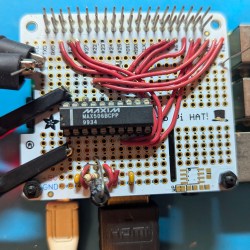
[jgpeiro] is no slouch when it comes to building small, affordable oscilloscopes out of common microcontrollers. His most recent, based on an RP2040 with two channels that ran at 100 MSps, put it on the order of plenty of commercially-available oscilloscopes at this sample rate but at a fraction of the price. He wanted to improve on the design though, making a smaller unit with a greatly reduced bill-of-materials and with a more streamlined design, so he came up with this STM32-based oscilloscope.

The goal of this project was to base as many of the functions around the built-in capabilities of the STM32 as possible, so in addition to the four input channels and two output channels running at 1 MHz, the microcontroller also drives a TFT display which has been limited to 20 frames per second to save processor power for other tasks. The microcontroller also has a number of built-in operational amplifiers which are used as programmable gain amplifiers, further reducing the amount of support circuitry needed on the PCB while at the same time greatly improving the scope’s capabilities.

In fact, the only parts of consequence outside of the STM32, the power supply, and the screen are the inclusion of two operational amplifiers included to protect the input channels from overvoltage events. It’s an impressive build in a small form factor, and we’d say the design goal of keeping the parts count low has been met as well. If you do need something a little faster though, his RP2040-based oscilloscope is definitely worth checking out.

Continue reading “STM32 Oscilloscope Uses All The Features”

The Simplest Curve Tracer Ever

To a lot of us, curve tracing seems to be one of those black magic things that only the true wizards understand. But as [DiodeGoneWild] explains, curve tracing really isn’t all that complicated, and it doesn’t even require specialized test instruments — just a transformer, a couple of resistors, and pretty much whatever oscilloscope you can lay your hands on.

True to his handle, [DiodeGoneWild] concentrates on the current-voltage curves of Zener diodes in the video below, mainly as a follow-up to his recent simple linear power supply project, where he took a careful look at thermal drift to select the best Zener for the job. His curve tracer is super simple — just the device under test in series with a bunch of 10-ohm resistors and the secondary winding of a 12-volt transformer. The probes of his oscilloscope — a no-frills analog model — go across the DUT and the resistor, and with the scope in X-Y mode, the familiar current-voltage curve appears. Sure, the trace is reversed, but it still provides a good visualization of what’s going on. The technique also works on digital scopes; just be ready for a lot of twiddling to get into X-Y mode and to get the trace aligned.

Of course it’s not just diodes that can be tested with a curve tracer, and [DiodeGoneWild] showed a bunch of other two-lead components on his setup. But for our money, the neatest trick here was using a shorted bridge rectifier to generate a bright spot on the curve to mark the zero crossing point. Clever indeed, and pretty useful on a scope with no graticule.

Continue reading “The Simplest Curve Tracer Ever”