Cheap Oscilloscope Is… Well… Cheap

We always enjoy watching [Kerry Wong] put an oscilloscope through its paces. His recent video is looking at a very inexpensive FNIRSI 1014D ‘scope that you can also find rebranded. You can usually find these for well under $200 at the usual places. Can you get a reasonable scope for that cost? [Kerry] has a list of issues with the scope ranging from short memory depth to low sensitivity. He did, however, like that it is USB powered so it can be operated from a common battery pack, which would make it truly floating.

The ‘scope looks like a lot of other inexpensive ‘scopes, but you can see some concessions to price. For example, the encoder knobs don’t have a push button function, making the scope more difficult to operate. While the specs are relatively modest, [Kerry] wasn’t sure the instrument was even living up to them.

Continue reading “Cheap Oscilloscope Is… Well… Cheap”

Cute Oscilloscope Uses LEDs For Display

Oscilloscopes were once commonly called CROs, for the fact that they relied on cathode ray tubes for display. Since then, technology has moved quickly, and oscilloscopes these days almost entirely rely on modern screens like LCDs. However, [lonesoulsurfer] went a different route with this fun DIY build, creating an oscilloscope with a low-resolution LED display.

Yes, the signals are shown on a 10×10 matrix made up of red LEDs. The individual pixels look nicely diffused and chunky thanks to the fact that [lonesoulsurfer] was able to source square 5mm LEDs for the build. The whole project only uses four ICs – a decade counter and a LM3914 LED driver to run the display, a 555 timer for clock input, and an LM386 op-amp for amplifying incoming signals.

With a mic fitted onboard, the oscilloscope can act as a simple music visualizer, or be used with a probe to investigate actual circuits. It may not be of great enough resolution or precision for fine work, but it’ll at least tell you if your microcontroller’s clock is running properly if you’re scratching your head about the function of a simple project.

We’ve seen some great DIY oscilloscopes over the years, like this neat Arduino-based build. Video after the break.

Continue reading “Cute Oscilloscope Uses LEDs For Display”

$60 PC Oscilloscope Review

Owning an oscilloscope is a real gamechanger and these days, scopes are more capable and less expensive than ever before. However, there is a big difference between scopes that cost several hundred dollars which are usually quite good and many of the very inexpensive — below $100 — instruments that are often — but not always — little more than toys. [Adrian] looks at a PC-based scope from Hantek that costs about $60. Is it a toy? Or a useful tool? He answers the question in the video below.

The Hantek 6022BE sports two channels with a 20 MHz bandwidth and 48 million samples per second. The device included probes, too. Of course, you also need a PC, although there is apparently third-party software for Android if you don’t want to lug a laptop around.

Continue reading “$60 PC Oscilloscope Review”

[Kerry Wong] Is Really Into Scope Meters

If a combination multimeter and oscilloscope is on your holiday shopping list this year, you might want to have a look at some of [Kerry Wong’s] recent videos on the subject. Over several videos he looks at — inside and out — an OWON HDS272S and a Hantek 2D72, both reasonably inexpensive entries in the field. Both instruments are similar and have a few variants depending on the frequency capability and the addition of a waveform generator.

There are several videos on the Hantek device that are a few months old, then some recent videos — like the one below — on the OWON device along with some comparison videos.

Continue reading “[Kerry Wong] Is Really Into Scope Meters”

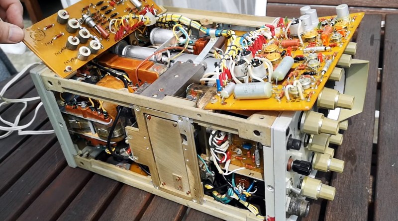
The insides of an oscilloscope

Oscilloscope Probes Itself To Add Video

Modern oscilloscopes are often loaded with features, but every now and then you run into a feature that seems easy to implement yet isn’t available. [kgsws] wanted to use his Rigol DS1074 to show live measurements in his YouTube videos, but found out that this scope doesn’t support video output. Not to be deterred, [kgsws] decided to add this feature himself. In the video embedded below, he describes in detail the process of adding a USB Video Capture (UVC) interface to his oscilloscope.

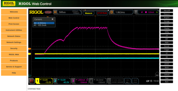
The basic idea was to find the signals going into the scope’s display and read them out using a Cypress EZ-USB board. This is a development board that can be used to design USB devices, and supports the UVC mode. However, with no documentation of any of the Rigol’s internal circuitry [kgsws] had to probe the display connector to find out which pin carried which signal. And since he had no other scope available than this Rigol, he hooked up the various bits of the disassembled instrument so that it could (awkwardly) probe its own internal signals.

After mapping out its own display signals, it was time to hook them up to the EZ-USB board. [kgsws] achieved this by soldering about two dozen tiny wires to SMD pads on the motherboard. The EZ-USB board itself was placed in the back of the scope’s case, but had to be stripped of unneeded components in order to save space and power. A very clever trick was the addition of a reed switch, which allowed [kgsws] to set the EZ-USB board to programming mode without having to open the scope’s case, by simply holding a magnet near the switch.

After soldering a USB connector into a spare slot in the RF shield the project was complete. The Rigol can now be connected to a PC and will simply appear as a video capture device, ready to be streamed or captured for [kgsws]’s future project videos. We’ve seen other hacks on the Rigol DS1000Z series to capture a series of screenshots or to enable additional bandwidth and features, but adding a live video output was not one of the options so far. Continue reading “Oscilloscope Probes Itself To Add Video”

Flip-Dot Oscilloscope Is Flippin’ Awesome

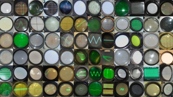
Oscilloscope displays have come a long way since the round phosphor-coated CRTs that adorned laboratories of old. Most modern scopes ship with huge, high-definition touch screens that, while beautiful, certainly lack a bit of the character that classic scopes brought to the bench. It’s a good thing that hackers like [bitluni] are around to help remedy this. His contribution takes the form of what may be both the world’s coolest and least useful oscilloscope: one with a flip-dot display.

Yup — a flip-dot display, in all it’s clickedy-clacky, 25×16 pixel glory. The scope can’t trigger, its maximum amplitude is only a couple of volts, and its refresh rate is, well, visible, but it looks incredible. The scope is controlled by an ESP32, which reads the analog signal being measured. It then displays the signal via an array of driver ICs, which allow it to update the dots one column at a time by powering the tiny electromagnets that flip over each colored panel.

Even better, [bitluni] live-streamed the entire build. That’s right, if you want to watch approximately 30 hours of video covering everything from first actuating a pixel on the display to designing and assembling a PCB to drive it, then you’re in luck. For the rest of us, he was kind enough to make a much shorter summary video you can watch below. Of course, this scope doesn’t runĀ Doom like some others, but its probably only a matter of time.

Thank to [Zane Atkins] for the tip!

Continue reading “Flip-Dot Oscilloscope Is Flippin’ Awesome”

Oscilloscope Clocks: Now In Color!

Ordinarily, when we hear the words “clock” and “oscilloscope” in the same sentence we conjure images of measuring a stable, repeating square wave that acts as the heartbeat of a system. Of course, that’s not the only meaning– there’s a much more fun and less useful one: using an oscilloscope to display the time.

That’s what [Wolfgang Friedrich] set out to do when he cobbled some protoboard, probes, and an FPGA into the Multi Color Oscilloscope Clock. Each digit on the clock is treated like a seven-segment display, made up of three horizontal bars and four vertical bars. The horizontal bars are generated by constant voltage at different levels, and the vertical bars are generated by quickly switching between two voltages. [Wolfgang] decided to use an R-2R resistor ladder DAC to create the appropriate analog signals from the FPGA’s digital outputs. For bonus points, each set of digits (hours, minutes, and seconds) are output concurrently through separate channels, so they can be displayed in different colors on the screen of his four-channel scope (the fourth channel is used for the points between numbers).

Misusing oscilloscopes in the name of fun has become a time-honored tradition– from Tennis for Two back in 1958 (which later became the beloved Pong) to the plethora of analog o-scope clocks we’ve seen, it’s clear that hackers just can’t get enough of the unique vector display style that a scope can provide. We love [Wolfgang]’s idea of using the scope’s channels to create a multi-color display, and we’re left wondering what kind of wacky waveforms we’ll be seeing next.