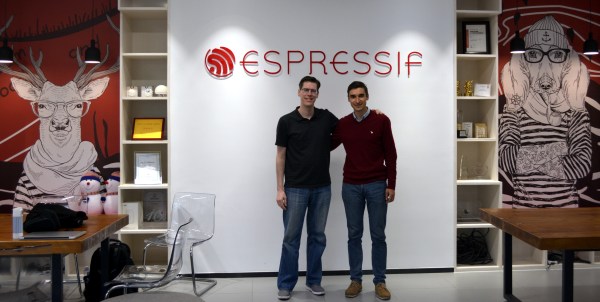
Thursday was my final day in Shanghai. After spending all of Wednesday at Electronica Asia, I headed over to the Espressif Headquarters which is just one subway stop away. This is of course the company behind the well-known ESP8266 and its younger sibling, the ESP32. My host was Ivan Grotkothov, Director of Software Platforms. The backstory on how he found his way to the company is truly interesting, as are the stories he shared on some of the legend and lore surrounding the WiFi capable chips the company makes — and the new one whose existence just leaked out this week.
Join me below for that and few other fun things from my last day in this city of 26 million people.
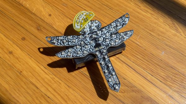
A couple years ago I got into making electronic conferences badges by building a device for DEFCON 25 shaped like a dragonfly. Like all badges the most important design factor was quite literally how flashy it was, and two years ago I delivered on that with ten RGB LEDs. At the time I planned to hand-assemble each and every of the 105 badges at my kitchen table. Given those constraints, and a desire for electrical and programmatic simplicity, I landed on using APA102s (DotStar’s in Adafruit parlance) in the common 5050 sized package. They were easy to place, easy to design with electrically, simple to control, and friendly to a human pick-n-place machine. Though by the end of the production run I had discovered a few problems, the APA102s were a success.
This year I made a new and improved version of the dragonfly, but applying my lessons learned led me to choose a very different LED architecture than 2017. I swapped out the smart LEDs for dumb ones.
After this Spring’s Bay Area Maker Faire closed down for Saturday night and kicked everybody out, the fun moved on to O’Neill’s Irish Pub where Hackaday and Tindie held our fifth annual meetup for fellow Maker Faire attendees. How do we find like-minded hackers in a crowded bar? It’s easy: look for tables lit by LEDs and say hello. It was impossible to see everything people had brought, but here are a few interesting samples.
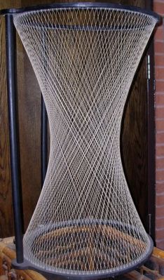
Death Stars were destroyed twice in the Star Wars movies and yet one still lives on in this 168 LED persistence of vision globe made by an MEng group at the University of Leeds in the UK. While Death Stars are in high demand, they mounted it on an axis tilted 23.4° (the same as the Earth) so that they can show the Earth overlaid with weather information, the ISS position, or a world clock.
More details are available on their system overview page but briefly: rotating inside and mounted on the axis is a Raspberry Pi sending either video or still images through its HDMI port to a custom made FPGA-based HDMI decoder board. That board then controls 14 LED driver boards mounted on a well-balanced aluminum ring. All that requires 75W which is passed through a four-phase commutator. Rotation speed is 300 RPM with a frame rate of 10 FPS and as you can see in the videos below, it works quite well.
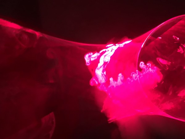
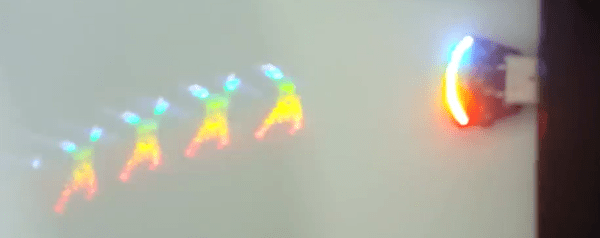
Everyone knows you can’t visibly bend light over short distances in free air. Or can you? [Jack Pearse] has figured out a way to do it though, or at least make it appear that way. He does it by combining a trick of math and a trick of the eye. The secret is the hyperboloid, a geometric construct described by a quadratic equation. [Jack’s] creation is more specifically a hyperboloid in one sheet. This type of structure allows straight lines to create a an overall curved surface. Hyperboloids have been used by architects and in construction for years, often in tall structures like water towers.
If a bunch of straight steel beams can form a curved shape, lasers should be able to pull off the same effect. By employing persistence of vision, [Jack] was able to create his hyperboloid with only 10 small lasers. The lasers are mounted on the rim of a bicycle wheel and carefully aimed. The wheel is spun up with using an electric bicycle motor. [Jack] kept things safe by building a centrifugal switch. The switch powers up all the lasers in when the tire is spinning. This ensures no one can be hit by a static beam.
Once the wheel is spinning, all you need is a bit of smoke or haze in the room. The spinning lasers combine to form the hyperboloid shape. You can see the project in action in the video after the break.
As the story goes, years ago [Matt Evans] was wooing the beautiful and talented [Jen]. There were many suitors vying for her hand; he would have to set himself apart. The trouble was, how to convince her that persisting in the relationship was the best and only course? What did he have to offer? Of course many of us know the answer; having wooed our own significant others with the same thing. Incredible and unrepentant nerdiness.
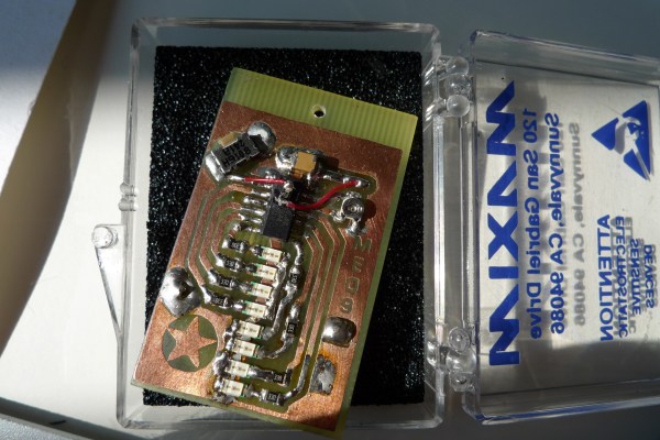
So! He toiled late into the night, his eyes burning with love and from the fumes of solder smoke. For her he would put his wizardry to work. At the wave of a hand would write songs of adoration in the air with nothing but light. The runes of power, all typed out in the proper order, would be held by a ATiny. A CR2032 coin cell provided the magic pixies which would march to its commands, delivering their spark to the LEDs in the right order.
He etched the board, wrote the code, and soldered the components. He encased it in his finest box of crystal clear plastic and black static foam, a gift of the samples department of the Maxim corporation.
Presumably the full moon was high in the air when he presented the box. He took it out and waved it with a flair. Poetry floated there in front of her eyes. It read, “Jen is cool!”. A few years later, they were married.
You think you’ve seen everything that there is to see regarding blinking LEDs and then a simple little trick proves you wrong. Our friend [Zach Fredin], aka [Zakqwy], added a pander mode to his blinky board which shows the Hackaday Jolly Wrencher in a Persistence of Vision mode. We love pandering, and obviously you just need to start the mode and wave the board back and forth. But in thinking the obvious you’d be wrong.
Badass deadbug soldering to “fix” a mirrored shift register footprint
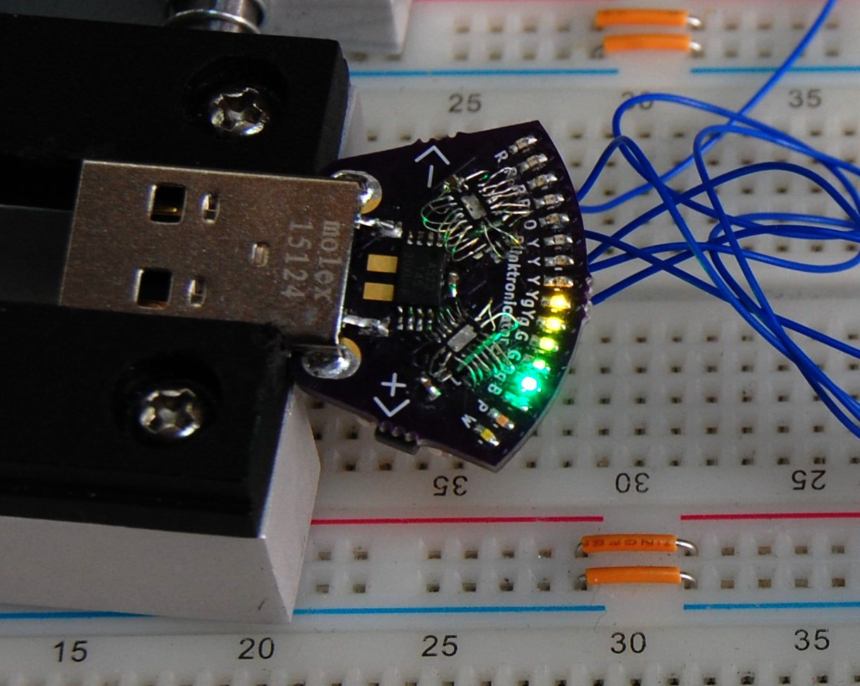
In the video after the break [Zach] demonstrates all the features of the blinktronicator and it’s recently finalized firmware. The tiny little board is a USB dongle featuring two buttons and an arc of sixteen LEDs in a rainbow of colors. When we say tiny, we mean it. Those LEDs are 0402 components and the board was small enough (and interesting enough) to receive an honorable mention in the Square Inch Project.
You would think that soldering all those LEDs by hand would be the trick, but [Zach] pulled off a much more difficult feat. Look closely at the image here (or click to embiggen). The two shift register footprints on the prototype were mirrored. He deadbug soldered each of them using — get this — the individual strands from some 28 AWG stranded wire. You sir, get the hardcore hand soldering badge and then some.
Okay, we’ll stop beating around the bush. The ATtiny45 on this board isn’t connected to the USB data lines, they’re only for power. That means, at its heart this is purely a blinking LED project, albeit one that uses the huge range of colors of the PICOLED family of parts. [Zach] did well with just two user inputs, but it’s the very simple POV party trick that really sucked us in. Instead of waving the board around, [Zach] uses a metal offset spatula as a mirror. Moving it back and forth unfolds the carefully timed flashes to draw your message in the air. Such a simple concept, but so satisfying to see it applied in a slightly different way.