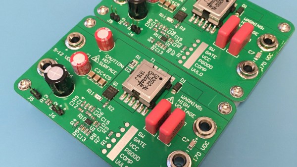
Switching Over To SMPS For Efficiency

[Hesam Moshiri] has built a variable switch-mode power supply over on hackaday.io. When prototyping a new circuit, often the goal is to get a proof-of-concept working as soon as possible to iron out all of the bugs it might have. The power supply can easily be an afterthought, and for smaller projects we might just reach for an adjustable LM317 voltage regulator to dial in the correct voltage and then move on with the meat of the project. These linear regulators are incredibly inefficient though, so if you find yourself prototyping with one of these often enough, it might be worthwhile to switch to something better.

While it’s easy to simply buy a switch-mode power supply (SMPS) that has everything you need, and rated for 90% or higher efficiency at the same time, getting one with an adjustable output isn’t as easy. This one is based on the relatively popular LM2576-Adj chip which handles the switching frequency part of the circuit automatically. You will also need some large capacitors, an inductor (one of the disadvantages of an SMPS circuit) and a small potentiometer to use as the feedback control for the LM2576. This special pin allows the output voltage of the SMPS to be precisely controlled.

Granted, this project might not be breaking any new grounds, but if you’ve never given serious thought to your small breadboard circuit power supplies, it’s definitely worth looking into. An improvement from a linear regulator’s 30% efficiency to 90% efficiency from an SMPS will not only save you a ton of energy but also solve a lot of heat dissipation problems. If you don’t want to build a switch-mode supply 100% from scratch, though, it might also be possible to modify an existing one to suit your needs as well.

Adding Bluetooth Control To A Benchtop Power Supply

In 2019, it’s possible to kit out a lab with all the essentials at an even cheaper price than it has ever been. The DPS3005 is one such example of low-cost equipment – a variable power supply available for less than $50 with a good set of features. [Markel Robregado] wanted a little more functionality, however, and got down to work.

The crux of [Markel]’s project is improved connectivity. A Texas Instruments CC2640R2F Launchpad is employed to run the show, with its Bluetooth Low Energy capability coming in handy. A custom smartphone app communicates with the Launchpad, which then communicates with the power supply over its Serial Modbus interface. Through the app, [Markel] can set the voltage and current limit on the power supply, as well as switch it on and off. This could prove useful, particularly for remote triggering in the case of working with dangerous projects. Sometimes it pays to take cover, after all.

We’ve seen power supplies modified before; this pot mod for higher precision is a particular treat. If you’ve hacked your bench hardware for better performance, let us know. Video after the break.

Continue reading “Adding Bluetooth Control To A Benchtop Power Supply”

A Breadboard Power Supply That’s More Universal Than Most

A favorite project of ours is the humble breadboard power supply. Yes, you can still prototype on breadboards, no, you don’t need an entire bench power supply to prototype on one, and every breadboard made in the last forty years has had the same pattern of holes. There’s plenty of opportunity to improve the breadboard power supply.

One of the best ones we’ve seen yet comes from [John Loeffler]. It’s a simple, constant voltage power supply that’s variable from 0.6 V all the way up to 12 V. It’s powered through a micro USB port, and you get 3.3 V and 5 V rails automagically. There’s even voltage indication.

The mechanical design of this power supply is simple enough, with pins that plug into the detachable power rails on either side of the breadboard. Where it gets interesting is the voltage indication. There’s a resistor ladder and a series of LEDs to indicate the voltage on the variable side of this power supply. Add in some modern switched mode power supply based on the MIC5225 series of chips (a popular regulator that’s very nice for the price) and you have a completely functional power supply hanging off a breadboard.

While it’s not a really nice rack mounted bench power supply that weighs a lot, or even one of the cheapo bench supplies, this does fulfill a need. Sometimes you just need a simple power supply for a breadboard, and this is one of the best ones we’ve seen yet.

Nixie Power Supply Shows Ins And Out Of Offshore Manufacturing

[Tony] built a high-efficiency power supply for Nixie tube projects. But that’s not what this post is about, really.

As you read through [Tony]’s extremely detailed post on Hackaday.io, you’ll be reading through an object lesson in electronic design that covers the entire process, from the initial concept – a really nice, reliable 170 V power supply for Nixie tubes – right through to getting the board manufactured and setting up a Tindie store to sell them.

[Tony] saw the need for a solid, well-made high-voltage supply, so it delved into data sheets and found a design that would work – as he points out, no need to reinvent the wheel. He built and tested a prototype, made a few tweaks, then took PCBWay up on their offer to stuff 10 boards for a mere $88. There were some gotchas to work around, but he got enough units to test before deciding to ramp up to production.

Things got interesting there; ordering full reels of parts like flyback transformers turned out to be really important and not that easy, and the ongoing trade war between China and the US resulted in unexpected cost increases. But FedEx snafus notwithstanding, the process of getting a 200-unit production run built and shipped seemed remarkably easy. [Tony] even details his pricing and marketing strategy for the boards, which are available on Tindie and eBay.

We learned a ton from this project, not least being how hard it is for the little guy to make a buck in this space. And still, [Tony]’s excellent documentation makes the process seem approachable enough to be attractive, if only we had a decent idea for a widget.

Mains Power Supply For ATtiny Project Is Probably A Bad Idea

When designing a mains power supply for a small load DC circuit, there are plenty of considerations. Small size, efficiency, and cost of materials all spring to mind. Potential lethality seems like it would be a bad thing to design in, but that didn’t stop [Great Scott!] from exploring capacitive drop power supplies. You know, for science.

The backstory here is that [Great Scott!] is working on a super-secret ATtiny project that needs to be powered off mains. Switching power supplies are practically de rigueur for such applications, but compared to the intended microcontroller circuit they are actually quite large, and they’ve just been so done before. So in order to learn a thing or two, [Scott!] designed a capacitive dropper supply, where the reactance of the cap acts like a dropping resistor to limit the current. His first try was just a capacitor in series with an LED; this didn’t end well for the LED.

To understand why, he reverse-engineered a few low-current mains devices and found that practical capacitive droppers need a few more components, chiefly a series resistance to prevent inrush current from getting out of hand, but also a bridge rectifier and a zener to clamp things down. Wiring up all that resulted in a working capacitive dropper supply, but a the cost of as much real estate as a small switcher, and with the extra bonus of being potentially lethal if the power supply is plugged in the wrong way. Side note: we thought German line cords were polarized to prevent this, but apparently not? (Ed Note: Nope!)

As always, even when [Great Scott!]’s projects don’t exactly work out, like a suboptimal 3D-printed BLDC or why not to bother building your own DC-AC inverter, we enjoy the learning that results.

Continue reading “Mains Power Supply For ATtiny Project Is Probably A Bad Idea”

Well-Protected USB Power Strip Makes It Easy To Plug In

When we get a new device these days, somewhere in the package is likely to be a wall-wart USB power supply. We look for a place to plug in the little switch-mode dongle, rearrange a few plugs in the mains power strip, and curse its designers for the overly cozy outlet spacing. And all the while that USB-A plug on the power supply cable taunts us with its neat, compact form factor. If only there were a USB power strip.

Unwilling to suffer such indignity any longer, [Scott M. Baker] took matters into his own hands and designed this USB power distribution system. We were surprised to hear that he was unable to find a commercial USB power strip, but even if he had, it likely wouldn’t have had the bells and whistles that he added to his. The circuit went through a couple of revs, but each was focused on protection of the connected USB devices. He included both overcurrent protection, in the form of an electronic fuse built around a TPS2421 hot-swap controller, and overvoltage protection using a crowbar circuit with the usual zener-SCR arrangement. There’s also a transient voltage suppression diode to keep any inductive spikes at bay. Interestingly, each USB outlet has all these protections – it’s not just one protected bus feeding a bunch of USB outlets in parallel, but individual modules with all the circuitry. The modules are gangable and live inside a laser-cut acrylic case. The video below shows the design and build process in some detail.

We have to say that we always learn a lot about circuit design from [Scott]’s projects. You may recall his custom Atari 2600 controller or his dual-port memory retro game console, both interesting and instructive builds in their own right.

Continue reading “Well-Protected USB Power Strip Makes It Easy To Plug In”

Travelling The Oregon Trail With An Apple II Robot

For one reason or another, we’re going with a retro-futuristic 80s aesthetic in this case, [Mike] decided to turn an Apple IIe into a robot. If you have to ask why, you’ll never know, but this project does have some interesting things going for it. There’s a voice synthesizer, a brand spankin’ new power supply, and it rolls around on the floor thanks to Apple BASIC.

Since this is a mobile robot, there needs to be a power supply in there somewhere. The Apple II had a fantastic switching power supply, but it ran off mains voltage. To make this Apple run off a 14.8 V LiPO battery, [Mike] needed to re-engineer this power supply to give +5, +12, -5, and -12 Volts. The easiest is the positive voltage, and for that, he used a big ‘ol LM1084 linear regulator for the +5 V line. This outputs a ton of heat and probably isn’t the best solution, but it is a solution that works. The +12 line was again another linear regulator, an LM7812CV. Since this is dropping 14.8 V down to 12, the efficiency isn’t that bad, and since there’s no floppy drive it’s not pulling much current anyway. The negative voltages are a MAX764 / MAX765 inverting switching regulators. This completely replaces the original power supply in the Apple II, and is a decent reference design for anyone who wants to make a luggable Apple II laptop.

To move this thing around, the motors run on their own 11.1 V LiPO, with a bunch of Pololu gear tying everything together. The BASIC code was written on an emulator, transferred over with the Floppy Emu. Movement is controlled through the output pins on the joystick port, and there’s a text to speech module that was obviously needed and ties this project together wonderfully. You can check out the video demo of the build below.

Continue reading “Travelling The Oregon Trail With An Apple II Robot”