Precision Reference Puts Interesting Part To Work

Interesting parts make for interesting projects, and this nifty precision voltage reference has some pretty cool parts, not to mention an interesting test jig.

The heart of [Gaurav Singh]’s voltage reference is an ADR1399, precision shunt reference from Analog Devices. The datasheet makes for pretty good reading and reveals that there’s a lot going on inside the TO-49 case, which looks unusually large thanks to a thick plastic coat. The insulation is needed for thermal stability for the heated Zener diode reference. The device also has a couple of op-amps built in, one that provides closed-loop voltage control and another that keeps the internal temperature at a toasty 95°C. The result is a reference that’s stable over a wide range of operating conditions.

[Gaurav]’s implementation maximizes this special part’s capabilities while making it convenient to use. The PCB has a precision linear regulator that accepts an input voltage from 16 V to 20 V, plus a boost converter that lets you power it from USB-C. The board itself is carefully designed to minimize thermal and mechanical stress, with the ADR1399 separated from the bulk of the board with wide slots. The first video below covers the design and construction of an earlier rev of the board.

One problem that [Gaurav] ran into with these boards was the need to age the reference with an extended period of operation. To aid in that, he built a modular test jig that completed PCBs can be snapped into for a few weeks of breaking in. The jigs attach to a PCB with pogo pins, which mate to test points and provide feedback on the aging process. See the second video for more details on that.

Continue reading “Precision Reference Puts Interesting Part To Work”

Retrotechtacular: The Tyranny Of Large Numbers

Although much diminished now, the public switched telephone network was one of the largest machines ever constructed. To make good on its promise of instant communication across town or around the world, the network had to reach into every home and business, snake along poles to thousands of central offices, and hum through the ether on microwave links. In its heyday it was almost unfathomably complex, with calls potentially passing through thousands of electronic components, any of which failing could present anything from a minor annoyance to a matter of life or death.

The brief but very interesting film below deals with “The Tyranny of Large Numbers.” Produced sometime in the 1960s by Western Electric, the manufacturing arm of the Bell System, it takes a detailed look at the problems caused by scaling up systems. As an example, it focuses on the humble carbon film resistor, a component used by the millions in various pieces of telco gear. Getting the manufacturing of these simple but critical components right apparently took a lot of effort. Initially made by hand, a tedious and error-prone process briefly covered in the film, Western Electric looked for ways to scale up production significantly while simultaneously increasing quality.

While the equipment used by the Western engineers to automate the production of resistors, especially the Librascope LGP-30 computer that’s running the show, may look quaint, there’s a lot about the process that’s still used to this day. Vibratory bowl feeders for the ceramic cores, carbon deposition by hot methane, and an early version of a SCARA arm to sputter gold terminals on the core could all be used to produce precision resistors today. Even cutting the helical groove to trim the resistance is similar, although today it’s done with a laser instead of a grinding wheel. There are differences, of course; we doubt current resistor manufacturers look for leaks in the outer coating by submerging them in water and watching for bubbles, but that’s how they did it in the 60s.

The productivity results were impressive. Just replacing the silver paint used for terminal cups with sputtered gold terminals cut 16 hours of curing time out of the process. The overall throughput increased to 1,200 pieces per hour, an impressive number for such high-reliability precision components, some of which we’d wager were still in service well into the early 2000s. Most of them are likely long gone, but the shadows cast by these automated manufacturing processes stretch into our time, and probably far beyond.

Continue reading “Retrotechtacular: The Tyranny Of Large Numbers”

Misleading GPS, Philosophy Of Maps, And You

The oft-quoted saying “all models are wrong, but some are useful” is a tounge-in-cheek way of saying that at some level, tools we use to predict how the world behaves will differ from reality in some measurable way. This goes well beyond the statistics classroom it is most often quoted in, too, and is especially apparent to anyone who has used a GPS mapping device of any sort. While we might think that our technological age can save us from the approximations of maps and models, there are a number of limitations with this technology that appear in sometimes surprising ways. [Kyle] has an interesting writeup about how maps can be wrong yet still be incredibly useful especially in the modern GPS-enabled world. Continue reading “Misleading GPS, Philosophy Of Maps, And You”

The Case Against Calibration Cubes

Calibration cubes have long been a staple for testing and adjusting 3D printers, but according to [Stefan] of CNC Kitchen, they’re not just ineffective—they could be leading us astray. In the video after the break he explains his reasoning for this controversial claim, and provides a viable alternative.

Such cubes are often used to calibrate the steps per millimeter for the printer’s steppers, but the actual dimensions of said cube can be impacted by over or under extrusion, in addition to how far the machine might be out of alignment. This can be further exacerbated by measuring errors due to elephant’s foot, over extruded corners, or just inaccuracies in the caliper. All these potential errors which can go unnoticed in the small 20 x 20 mm cube, while still leading to significant dimensional errors in larger prints

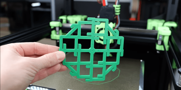
So what’s the solution? Not another cube. It’s something called the “CaliFlower” from [Adam] of Vector 3D. This is not a typical calibration model — it’s carefully designed to minimize measurement errors with ten internal and external measuring points with stops for your calipers. The model costs $5, but for your money you get a complete guide and spreadsheet to calculate the required of corrections needed in your firmware or slicer settings.

If you regularly switch materials in your 3D printer, [Stefan] also advises against adjusting steps per millimeter and suggests defining a scaling factor for each material type instead. With this method validated across different materials like PLA, PETG, ABS, and ASA, it becomes evident that material shrinkage plays a significant role in dimensional inaccuracy, not just machine error. While [Stefan] makes a convincing case against the standard calibration cube for dimensional calibration, he notes that is is still useful for evaluating general print quality and settings.

[Stefan] has always done rigorous testing to back his claims, and this video was no different. He has also tested the effects of filament color on part strength, the practicality of annealing parts in salt, and even printing custom filament.

Continue reading “The Case Against Calibration Cubes”

Hackaday Prize 2023: Over-the-Top Programmable Resistor Looks The Part And Performs

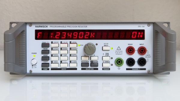
Every once in a while we get wind of a project that we’re reluctant to write up for the simple reason that it looks too good to be true. Not that projects need to be messy to be authentic, mind you, but there are some that are just so finished and professional looking that it gives us a bit of pause. [Sebastian]’s programmable precision resistor is a shining example of such a project

While [Sebastian] describes this as “a glorified decade resistance box,” and technically that’s exactly right — at its heart it’s just a bunch of precision resistors being switched into networks to achieve a specific overall resistance — there’s a lot more going on here than just that. The project write-up, which has been rolling out slowly over the last month or so, has a lot of detail on different topologies that could have been used — [Sebastian] settled on a switched series network that only requires six relays per decade while also minimizing the contribution of relay contact resistance to the network. Speaking of which, there’s a detailed discussion on that subject, plus temperature compensation, power ratings, and how the various decades are linked together.

For as much that’s interesting about what’s under the hood, we’d be remiss to not spend a little time praising the exterior of this instrument. [Sebastian] appears to have spared no expense to make this look like a commercial product, from the rack-mount enclosure to the HP-esque front panel. The UI is all discrete pushbuttons and knobs with a long string of 16-segment LEDs — no fancy touch-screens here. The panel layout isn’t overly busy, and looks like it would be easy to use with some practice. We’d love to hear how the front and rear panel overlays were designed, too; maybe in a future project update.

This honestly looks like an instrument that you’d pay a princely sum to Keithley or H-P to own, at least back in the late 1990s or so. Kudos to [Sebastian] for the attention to detail here.

Learn How Impossibly Close-fitting Parts Are Actually Made

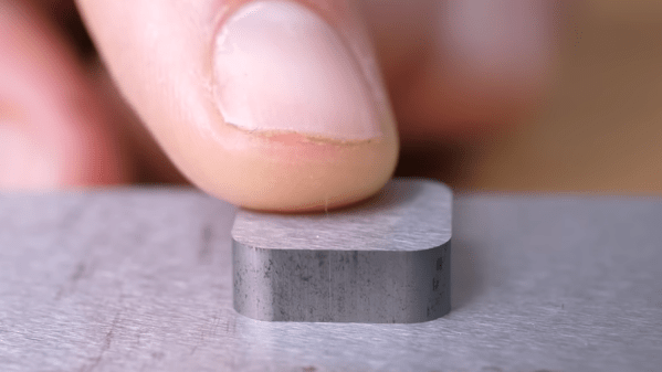
Most of us have seen those demonstrations of metal parts that mate together so finely that, once together, they have no visible seam at all. But how, exactly, is this done? [Steve Mould] has a video that shows and explains all, and we’ve never seen the process explained quite like he does.

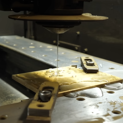
The secret ingredient is wire EDM, or Electrical Discharge Machining, but that’s only one part of the whole. Wire EDM works a bit like a hot-wire cutter slicing through foam, but all by itself that’s not enough to produce those impossibly close-fitting parts we love to see.

EDM is capable of astounding precision in part because — unlike a cutting tool — nothing physically contacts the material. Also, there isn’t a lot of friction and heat causing small distortions of the material during the machining process. EDM is as a result capable of fantastically-precise cuts, but not invisible ones.

It’s pretty neat to see a water jet used to thread the fine wire through the workpiece.

In all good manufacturing, the capabilities (and limitations) of the tool are taken into account, and this is also true for making those close-fitting pieces. The hole and plug are actually made in two separate stages.

The hole is cut separately from the plug, and because EDM is capable of such finesse, the cuts can be made in such a way that they complement one another with near-perfection. After that, grinding and polishing takes care of the surface finish. The result is the fantastically-smooth and apparently seamless fitment we like so much.

The video is embedded below, and there are some great details about EDM and how it actually works in there. For example, we see how a wire EDM machine can use a jet of water to help thread the wire through a hole in the part to start a job, and we learn that the wire is constantly moving during the process.

As cool as wire EDM is, it is not magic and we’ve seen some pretty remarkable efforts at bringing the technology into the home workshop.
Continue reading “Learn How Impossibly Close-fitting Parts Are Actually Made”

Metric And Inch Threads Fight It Out For Ultra-Precise Positioning

When you’re a machinist, your stock in trade is precision, with measurements in the thousandths of your preferred unit being common. But when you’re a diemaker, your precision game needs to be even finer, and being able to position tools and material with seemingly impossibly granularity becomes really important.

For [Adam Demuth], aka “Adam the Machinist” on YouTube, the need for ultra-fine resolution machinist’s jacks that wouldn’t break the bank led to a design using off-the-shelf hardware and some 3D printed parts. The design centers around an inch-metric thread adapter that you can pick up from McMaster-Carr. The female thread on the adapter is an M8-1.25, while the male side is a 5/8″-16 thread. The pitches of these threads are very close to each other — only 0.0063″, or 161 microns. To take advantage of this, [Adam] printed a cage with compliant mechanism springs; the cage holds the threaded parts together and provide axial preload to remove backlash, and allows mounting of precision steel balls at each end to make sure the force of the jack is transmitted through a single point at each end. Each full turn of the jack moves the ends by the pitch difference, leading to ultra-fine resolution positioning. Need even more precision? Try an M5 to 10-32 adapter for about 6 microns per revolution!

While we’ve seen different thread pitches used for fine positioning before, [Adam]’s approach needs to machining. And as useful as these jacks are on their own, [Adam] stepped things up by using three of them to make a kinematic base, which is finely adjustable in three axes. It’s not quite a nanopositioning Stewart platform, but you could see how adding three more jacks and some actuators could make that happen.

Continue reading “Metric And Inch Threads Fight It Out For Ultra-Precise Positioning”