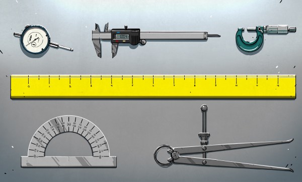
When you’re a machinist, your stock in trade is precision, with measurements in the thousandths of your preferred unit being common. But when you’re a diemaker, your precision game needs to be even finer, and being able to position tools and material with seemingly impossibly granularity becomes really important.
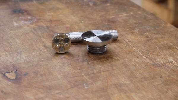
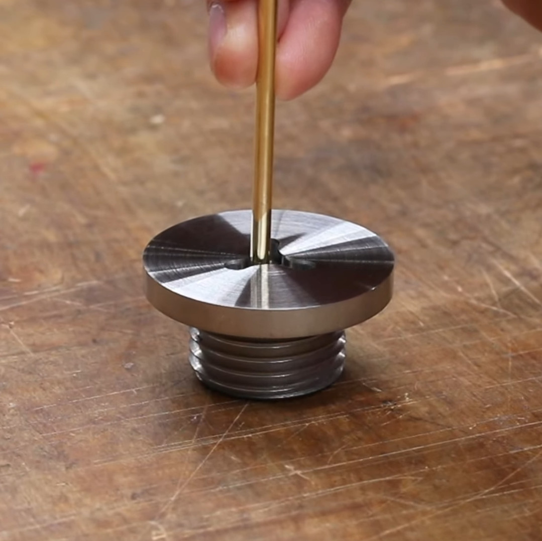
For [Adam Demuth], aka “Adam the Machinist” on YouTube, the need for ultra-fine resolution machinist’s jacks that wouldn’t break the bank led to a design using off-the-shelf hardware and some 3D printed parts. The design centers around an inch-metric thread adapter that you can pick up from McMaster-Carr. The female thread on the adapter is an M8-1.25, while the male side is a 5/8″-16 thread. The pitches of these threads are very close to each other — only 0.0063″, or 161 microns. To take advantage of this, [Adam] printed a cage with compliant mechanism springs; the cage holds the threaded parts together and provide axial preload to remove backlash, and allows mounting of precision steel balls at each end to make sure the force of the jack is transmitted through a single point at each end. Each full turn of the jack moves the ends by the pitch difference, leading to ultra-fine resolution positioning. Need even more precision? Try an M5 to 10-32 adapter for about 6 microns per revolution!
While we’ve seen different thread pitches used for fine positioning before, [Adam]’s approach needs to machining. And as useful as these jacks are on their own, [Adam] stepped things up by using three of them to make a kinematic base, which is finely adjustable in three axes. It’s not quite a nanopositioning Stewart platform, but you could see how adding three more jacks and some actuators could make that happen.
Continue reading “Metric And Inch Threads Fight It Out For Ultra-Precise Positioning”