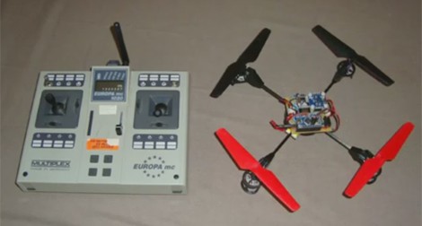
The Hexapod Hexacopter

Hexapod Hexacopter

Over at Mad Lab Industries, they had the idea of building a quadcopter that could walk and fly. By combining a hexapod with a hexacopter, they ended up with this creation.

The hexapod part started off with PhantomX Hexapod Kit, but it was far too heavy to fly. To reduce weight, they manufactured carbon fibre parts for the frame and legs. Even with the weight reductions, they still needed to six rotors to keep it stable.

The hexacopter part of the build uses more custom carbon fibre parts to mount the motors. The booms and mounts are also custom built out of aluminium. They used six E-Flite motors, propellers, and ESCs to provide lift.

A variety of controllers are used to run the robot. Two Arbotix devices handle the hexapod control, and a Hoverfly flight controller keeps it in the air. It’s controlled remotely using a Spektrum controller.

They have some ambitious next steps, including a mechanism that disconnects and reconnects the hexacopter and the base. After the break, check out a video of this impressive build in action.

Continue reading “The Hexapod Hexacopter”

Turning Four Smaller Helicopters Into One Larger Quadcopter

copter

There’s a reason we’ve seen a menagerie of quadcopters over the past few years – the key piece of any quadcopter build is an inertial measurement unit. Historically a very complicated and expensive piece of kit, these IMUs came down in price a few years back, allowing anyone with a few dollars in their pocket and a handful of brushless motors to build a four-bladed drone in their workshop.

[Starlino] built a few quadcopters, but he wanted to shy away from IMUs and get most of the mass of his new ‘copter over the center of the chassis. He came up with a design he calls the quadhybrid that can be built out of a quartet of those cheap 3-channel helicopter toys.

Most of the lift for [Starlino]’s quadhybrid comes from a pair of coaxial rotors from a Syma 001 3-channel helicopter toy. Anyone who has played with one of these toy helicopters knows how stable they are; if the tail rotor breaks, you’re left with a helicopter that can only go up and down.

To give his quadhybrid a few degrees of freedom, he attached four tail rotors from 3-channel helis to a few booms laid out in a cross pattern. By taking the receiver out of a 4-channel helicopter and adding his own controller board, [Starlino] made each of the tail rotors control the pitch and roll of the craft.

In the video after the break, you can see the quadhybrid is amazingly stable even without an IMU and surprisingly agile. As [Starlino]’s ‘copter can be made out of replacement parts for cheap 3-channel helis, we’ll expect a rush on these tail motors at your favorite online RC retailer very shortly.

Continue reading “Turning Four Smaller Helicopters Into One Larger Quadcopter”

Man Tracks Children Using A Quadcopter

child-tracking-quadcopter

Instead of walking his kid to the bus stop like he used to, [Paul Wallich] lets this quadcopter watch his son so he doesn’t have to. It is quite literally an automated system for tracking children — how wild is that?

The idea came to him when wishing there was a way to stay inside the house during the winter months while still making sure his kid got to the bus stop okay. [Paul] picked up a quadcopter kit and started looking at ways to add monitoring. He found the easiest technique was to include a cellphone and watch via a video chat app. But that is only part of the build as he would still have to fly the thing. After searching around he found a beacon that can be placed in the backpack. It has a GPS module, an RF modem, and runs a stripped down Python scripting shell. Whenever the GPS data changes (signaling his son is on the move) it uplinks with the quadcopter and gives it the new coordinates.

This goes a long way to making your family a police state. May we also recommend forcing the children to punch a time clock?

[via: theGrue]

Raspberry Pi Quadcopter

[youtube=http://www.youtube.com/watch?v=TjXvzMdf8Nk&w=470]

It was bound to happen sooner or later, but that doesn’t diminish the awesomeness of [Matthew]’s Raspberry Pi-powered quadcopter.

[Matthew]’s quadcopter is similar to all the other flying drones we’ve seen before with one important difference – all the processing, from reading the gyroscopes to computing exactly how much power to give each motor – is handled by a Raspberry Pi. This task is usually the domain of a microcontroller, as these calculations need to happen in real-time. The Linux distro [Matt] is running on his Pi has a lot more overhead than a simple AVR or ARM microcontroller, so doing everything that needs to be done in real-time isn’t guaranteed. With a bit of clever programming, [Matthew] managed to make sure all the necessary tasks were taken care of in time. It’s still not a real-time operating system, but for this project at least, it’s good enough.

Since the Raspberry Pi in [Matthew]’s quadcopter is much more powerful than a microcontroller, there’s plenty of head room to SSH into the ‘copter while it’s flying. There may even be enough processing power to stream video to a web server; we honestly can’t wait to see what [Matthew] does with his flying Linux computer in the future.

You can check out [Matthew]’s code over on the git or watch a few flight test videos over on his youtube.


Adding Node.js Based Sensors To The Parrot AR Drone

[Max Ogden] wanted the option to add sensors to his Parrot AR Drone. This a commercially available quadcopter which runs Linux. This makes it rather easy for him to use Node.js to read the sensors from an Arduino board. The use of the Arduino is merely for easy prototyping. It is only needed to bridge the drone’s serial port with a sensor’s delivery method, so just about any microcontroller could be substituted for it.

There are some hardware considerations to take into account. The manufacturer was nice enough to populate a 0.1″ pitch pin socket on the serial port (if only this kind of invitation to mess with hardware was an industry standard). But the device expects 3.3V levels so pick your hardware accordingly. There is one commenter who tried the project for themselves and found that the drone wouldn’t boot up with the Arduino already connect — he had to boot and then complete connections. Troubles aside this makes adding your own sensor payload very simple and you don’t have to wait until landing to get at the data.

Maybe we’ll have to add some shock voltage data reporting to our shockerDrone.

Building A Tilt Rotor UAV

We see a lot of quadcopters, and even the occasional octocopter around here. But this build does it with just two propellers. It’s a tiltrotor build which allows the two upward-pointing propellers to tilt forward and backward. The real world equivalent of this UAV design that pops to mind is the V-22 Osprey.

The motors are mounted on a beam running perpendicular to the direction of travel. Each of them is mounted on a bearing which can be rotated by a servo motor. They rotate independently of each other, which allows for yaw. Of course roll is controlled by driving the propellers at different speeds and pitch is adjusted by tilting both mounts at the same time.

[Stephen] mentions that the tiltrotor design has several advantages over its relatives that use more than two props. This design costs less to build, uses less electricity, and makes for an easier autopilot implementation. If you want to see it in the air, don’t miss the clip after the break.

This is just the second tiltrotor build we remember seeing. The other one was a Halloween prop.

Continue reading “Building A Tilt Rotor UAV”

Integrating A Power Bus Into A Quadcopter Frame

When working on flying vehicles weight is always a consideration. [Brendin] found a way to get rid of a wiring harness on his quadcopter, simplifying the assembly while lightening the load. He did it by incorporating the power bus into the frame of the vehicle.

He started with some copper clad board. Because the substrate is a structural component he didn’t want to use a CNC mill to do the etching as it also removes a bit more than just copper. After using the mill to cut out the shape and drill holes he coated the board with flat black paint. This acts as the etch resist, which he sent through a 50W laser engraver to remove the paint and expose the areas he wants to etch. After etching he removed the rest of the resist, and masked off his solder pads with small rectangles of electrical tape. This protects the solder pads from the truck bed liner paint he uses to insulate the copper. He says it works great and plans to use the technique on all future builds.