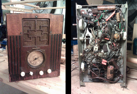
Very Inexpensive RF Module Tutorial

Let’s say you need a way to make a project wireless, but don’t have the scratch for a ZigBee or its ilk. You could use IR, but that has a limited range and can only work within a line of sight of the receiver. [Camilo] sent in a project (Spanish, translation) to connect two devices via a wireless serial connection. As a small bonus, his wireless setup is cheap enough to create a wireless network of dozens of sensors.

[Camilo] used the TLP434A transmitter/receiver combination to get his wireless project off the ground. These small devices only cost about $5, but being so inexpensive means the hardware designer needs to whip up their own communications protocol.

For a microcontroller, [Camilo] chose a Freescale MC9S08QC, a pleasant refrain from the AVR or PIC we normally see. After making a small board for his transmitter, [Camilo] had a very small remote control, able to send button presses or other data to a remote receiver.

After the break, you can see a short demo video [Camilo] posted of his wireless transmitter turning on an LED attached to his receiver. Unfortunately, this video was filmed with a potato, but all the schematics and code is on his web site for your perusal.

Continue reading “Very Inexpensive RF Module Tutorial”

Ancient Radio Repair

They sure don’t build them like that anymore. [J.W. Koebel] managed to take this 1934 Simplex Model P radio and bring it back to life.

So where do you start with a repair job like this one? Being a ham radio guy he has a good idea of what he’s doing, and started by replacing the AC capacitor with one which will provide quality noise filtering. He tried to make fixes throughout that would improve functionality and declutter the wire mess. This led him to find a snapped solder connection on the volume knob. Next he tested out the speaker and found that the primary transformer needed replacing. After as replacing the A67 converter (we’ve got no idea what that is) he swapped out the rest of the original capacitors, most of the resistors, and fixed the mechanical problems with the tuning dial. The result is a working radio that looks fantastic!

[via Reddit]

Building A Radio Telescope For A School Science Project

The image above is a picture of  Hydrogen emissions from our galaxy. The cool thing about this picture is it wasn’t taken with millions of dollars worth of equipment; instead, only a few hundred dollars worth of ham radio gear was needed to get a picture of the Milky Way. [Shanni Prutchi], with the help of her dad [David] built this radio telescope in 5th grade, and even gave a presentation on this build at the National Radio Astronomy Observatory.

Instead of a gigantic satellite dish, [Shanni] used a loop yagi antenna to collect radio signals in the 1420 MHz band. These signals are amplified, filtered, and sent to an ICOM IC R-7000 receiver specially modified by [Shanni]’s dad for radio astronomy.

After her telescope saw first light, [Shanni] and [David] decided to use their brand new toy to detect the passage of the sun. At around 10:00 am they pointed the telescope at where the sun would be at 1:30 pm. For the next few hours, the telescope gathered and integrated radio signals to make an awesome graph. Yep, [Shanni]’s scope can detect radio waves coming directly from the sun.

Like a lot of us, [Shanni] was very much influenced by the movie Contact, something we brought up last week in a post on software-defined radio telescopes. This telescope was built in 2005, meaning [Shanni] couldn’t take advantage of any of the new advances in cheap software radios. We’re still waiting for someone to throw a Realtek SDR telescope together, so if you’ve got one send it in

Working Software-defined Radio With A TV Tuner Card.

[Balint Seeber] just sent in a small yet timely project he’s been working on: a software radio source block for the Realtek RTL2832U. Now with a cheap USB TV tuner card, you can jump right into the world of software-defined radio.

[Balint]’s code comes just a week after hackaday and other outlets posted stories about using a $20 USB TV capture dongle for software defined radio. At the time, these capture cards could only write data directly to a file. With [Balint]’s work, anyone can use a cheap tv tuner dongle with HDSDR, Winrad, or GNU Radio. If you’ve ever thought about trying out software-defined radio, now might be the time.

Elsewhere on the Internet, a surprisingly active RTL-SDR subreddit popped up dedicated to using the Realtek RTL2832U tuner for software defined radio. There’s an awesome compatibility chart listing compatible USB dongles. The cheapest (so far, and subject to change) is the Unikoo UK001T available for $11 on eBay.

With his source block, [Balint] can listen to anything on the radio between 64-1700 MHz. The sample depth is 8 bits and the sample rate can be anything up to 3.2 MHz. You can watch [Balint] testing out his $20 GNU Radio rig after the break.

Continue reading “Working Software-defined Radio With A TV Tuner Card.”

Software Defined Radio From A USB TV Capture Card

With a simple digital TV USB capture card, you can build your own software defined radio or spectrum analyzer. While it may not be as cool as [Jeri Ellsworth]’s SDR, it’s still very useful and only requires $20 in hardware.

The only piece of hardware required for this build is a USB FM/DTV capture device with the Realtek RTL2832U chipset. So far, two USB sticks have been tested and the unit with the largest frequency range (64 – 1700 MHz) is available direct from China for $20.

Turning these cheap capture cards into software defined radios and spectrum analyzers was discovered by [Antti Palosaari] after sniffing the device. These cards demodulate the frequency and send all the data to the computer and is decoded via software. If you have one of these capture cards lying around, you can grab the software and load it up on your *nix box. Right now, the software only writes directly to a file, and may drop a few samples if writing to a hard disk instead of ram. Small problems, but we’re sure this project will pick up steam in the very near future.

via reddit

Old Radio + Old Phone = Android Media Station

[Bjørn] combined some aging electronics he had around the house to create this Android media center. The enclosure is an FM-radio, but since he only listens to online media it wasn’t of much use to him. After sizing it up he realized it was a perfect candidate to receive his old HTC Hero Android phone.

The upper portion of the stock radio used to host controls for tuning the FM dial, adjusting volume, and switching the unit on and off. He cracked open the case, ditching the radio receiver and patching in to the amplifier. The volume knob was moved to the right side of the case, and a hole cut to receive the phone. Audio is pulled from the phone with the jack sticking out the left side. We’d love to see a future improvement using a right-angle jack (kind of like this charging hack) or patched directly into the phone’s circuit board. This way everything would fit inside the box.

Now he can listen to Internet radio, or stream some video like in the clip after the break.

Continue reading “Old Radio + Old Phone = Android Media Station”

8-bit Computer Project Lands In A Philco Radio Case

We’ve enjoyed seeing the development progress of Veronica, [Quinn Dunki’s] 8-bit computer project. It started out on a breadboard, then moved to edge-connected PCBs, and now [Quinn] has given Veronica a body of her own.

The donor is a Philco Model 42-327T and was produced in 1942. It was chosen because it is non-functional and missing several pieces. We wonder about the collector’s value of the piece but since [Quinn] snagged it from eBay there can’t be in huge demand right now. The teardown images are priceless. There seems to be no reasoning behind component placement for the beast. It looks more like a junk drawer packed full of relic components than something that actually worked once upon a time.

But we digress. After gutting the retro wooden case [Quinn] set out to fabricate her own face plate. Since she’s comfortable working with copper clad, she whipped up a negative design and etched the dashboard seen above. It mounts in the original dial opening, and hosts all of the controls she needs to work with the 8-bit computer. Just below is where the present buttons used to be located. You can just see the hexout display for reading data from the registers mounted in that void.