Most people would be pretty upset it the lawn mower they spent $4,000 USD on had a major failure within the first year of owning it. But for [xxbiohazrdxx], it was an excuse to take a peek under the hood and figure out what brought down this state-of-the-art piece of landscaping gear.
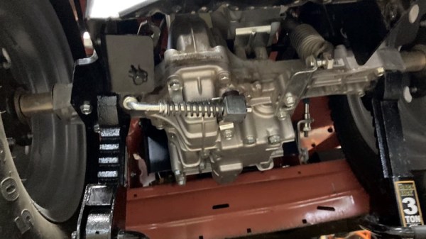
It should be said that, at least technically, the Husqvarna TS 348XD in question was still working. It’s just that [xxbiohazrdxx] noticed the locking differential, which is key to maintaining traction on hilly terrain, didn’t seem to be doing anything when the switch was pressed. Since manually moving the engagement lever on the transmission locked up the differential as expected, the culprit was likely in the electronics.
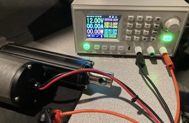
As [xxbiohazrdxx] explains, the switch on the dash is connected to a linear actuator that moves the lever on the transmission. The wiring and switch tested fine with a multimeter, but when the actuator was hooked up to a bench power supply, it didn’t move. Even more telling, it wasn’t drawing any power. Definitely not a good sign. Installing a new actuator would have solved the problem, but it was an expensive part that would take time to arrive.
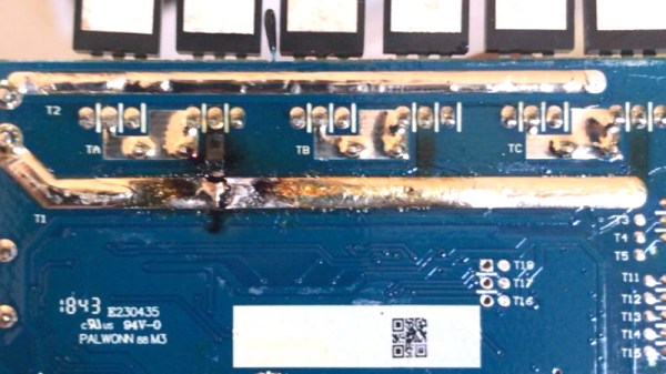
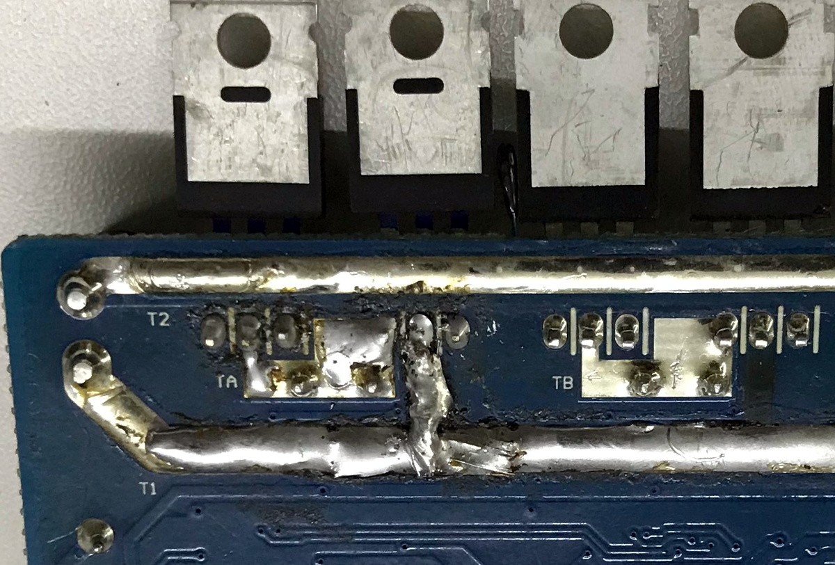
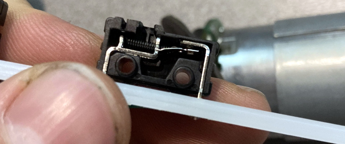
Repairing the dead actuator seemed worth a shot at least, so [xxbiohazrdxx] cracked it open. The PCB looked good, and there were no obviously toasted components. But when one of the internal microswitches used to limit the travel of the actuator was found to be jammed in, everything started to make sense. With the switch locked in the closed position, the actuator believed it was already fully extended and wouldn’t move. After opening the switch itself and bending the contacts back into their appropriate position, everything worked as expected.
As interesting as this step-by-step repair process was, what struck us the most is [xxbiohazrdxx]’s determination to fix rather than replace. At several points it would have been much easier to just swap out a broken part for a new one, but instead, the suspect part was carefully examined and coaxed back to life with the tools and materials on-hand.
While there’s plenty of folks who wouldn’t mind taking a few days off from lawn work while they wait for their replacement parts to arrive, not everyone can afford the luxury. Expedient repairs are critical when your livelihood depends on your equipment, which is why manufacturers making it harder and more expensive for farmers to fix their tractors has become such a major issue in right to repair battles all over the globe.